
Hydraulic control loops are pre-defined set of elements (blocks with 2 entry points and 2 exit points, pump, balancing valves, etc.) saved in manufacturers catalogue, implemented in a manner consistent with the requirements of the manufacturer of this system in scope of:
- Balancing and regulating the installation
- Sizing of valve diameters
- Determination of valve settings
- Determination of pump working parameters
- Observing and diagnostics of other guidelines (e.g. required valve authority or preferred settings)
Hydraulic control loops are a unique configuration distinguishing feature of the program because they are prepared to meet specific customer requirements and their functionality is impossible to implement with elements and functions available as standard in the program. The use of hydraulic control loops in the project is simple and limited to inserting the finished block, from a dedicated additional toolbar tab, into the selected installation location. Configuration of hydraulic control loops allows their wide application in heating and cooling installations (receptors of various types and surface systems) eliminating, at the same time, potential and difficult to diagnose design errors (e.g. by limiting the availability of valves that cannot be used in specific installation solutions).
In InstalSystem 5, the possibility of using hydraulic control loops depends on the availability of a separate module package configuration called ‘Hydraulic control loops’ and the required catalogues.

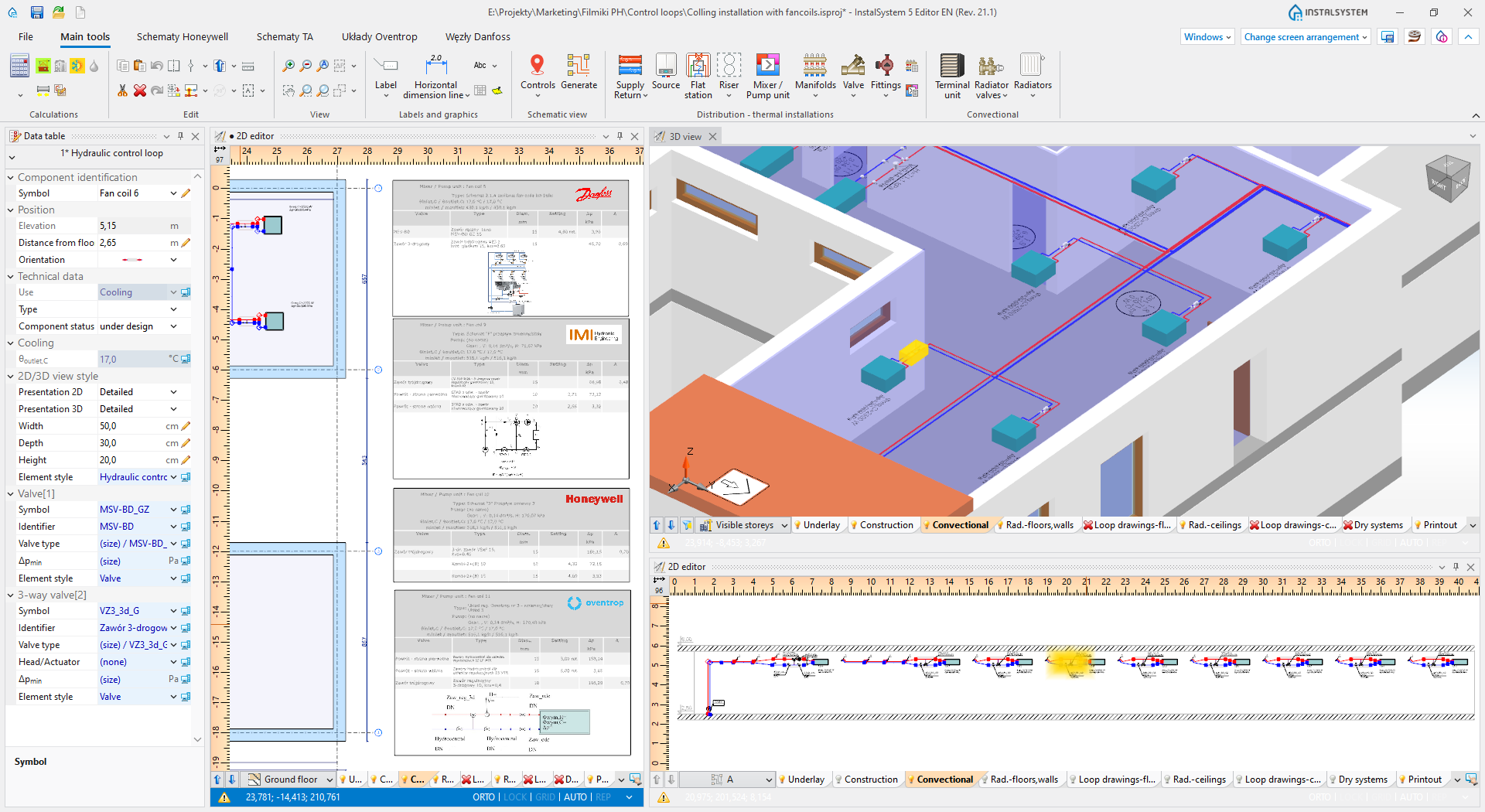
Watch also fragment of the tutorial about designing cooling systems, in which examples of hydraulic control loops are presented: