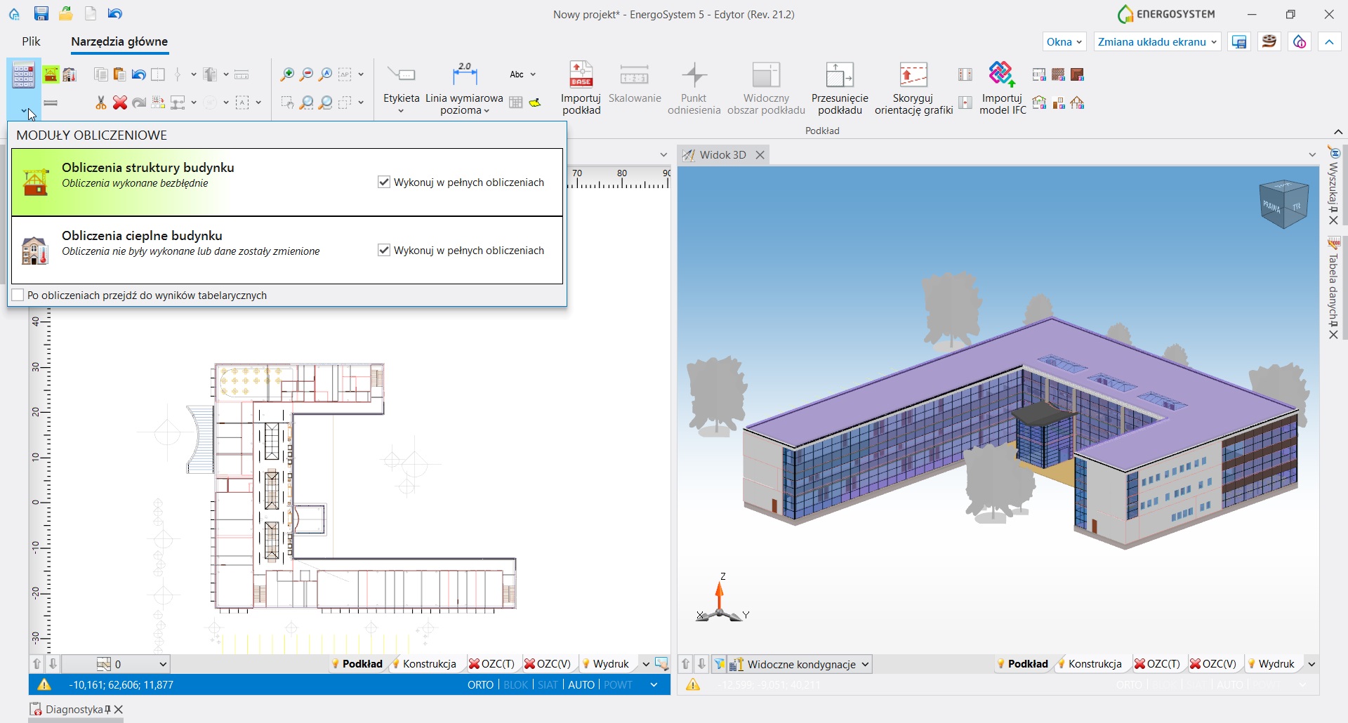
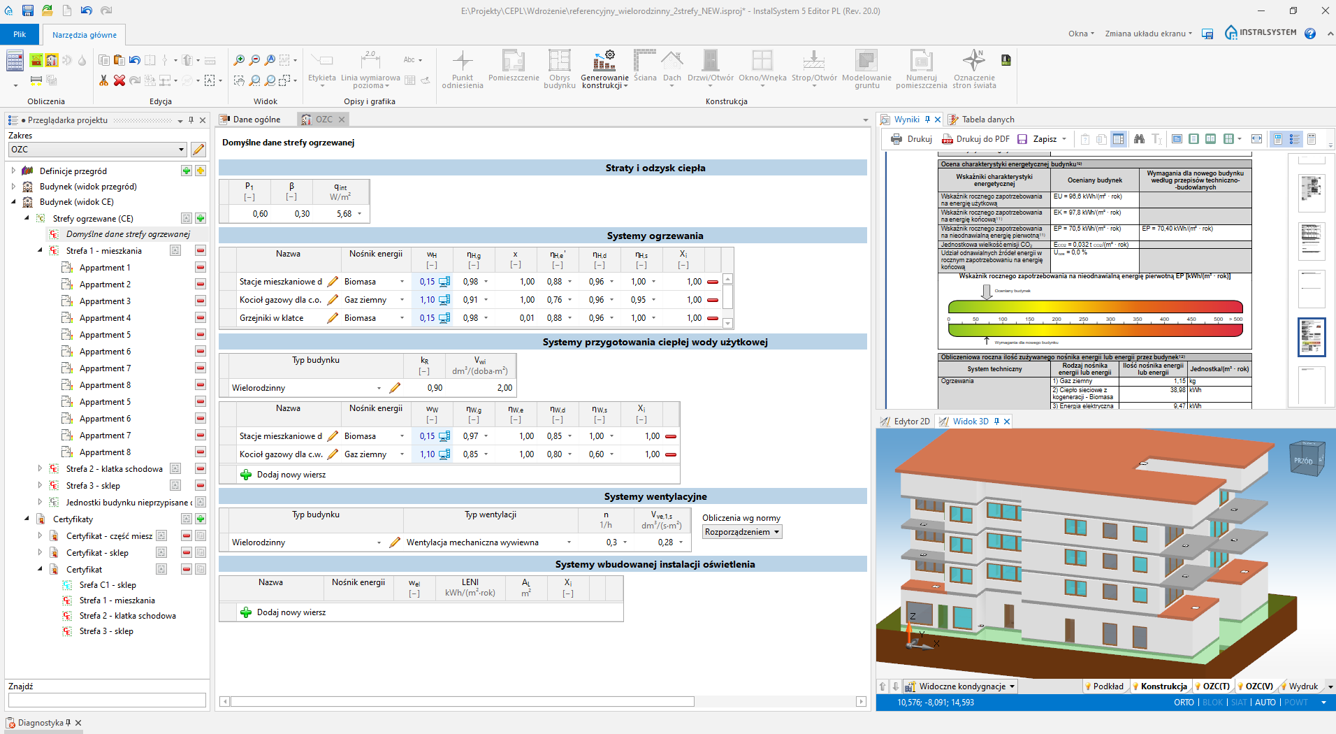
Pakiet EnergoSystem służy do obliczeń projektowego obciążenia cieplnego, wyznaczania charakterystyki energetycznej budynku i sporządzania świadectw charakterystyki energetycznej.
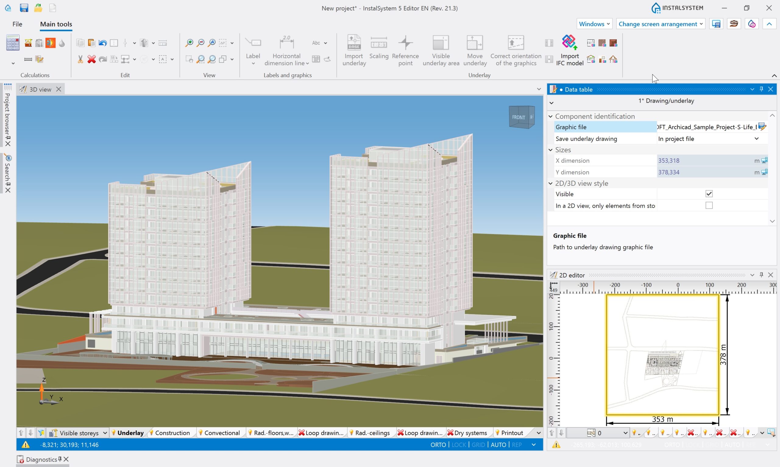
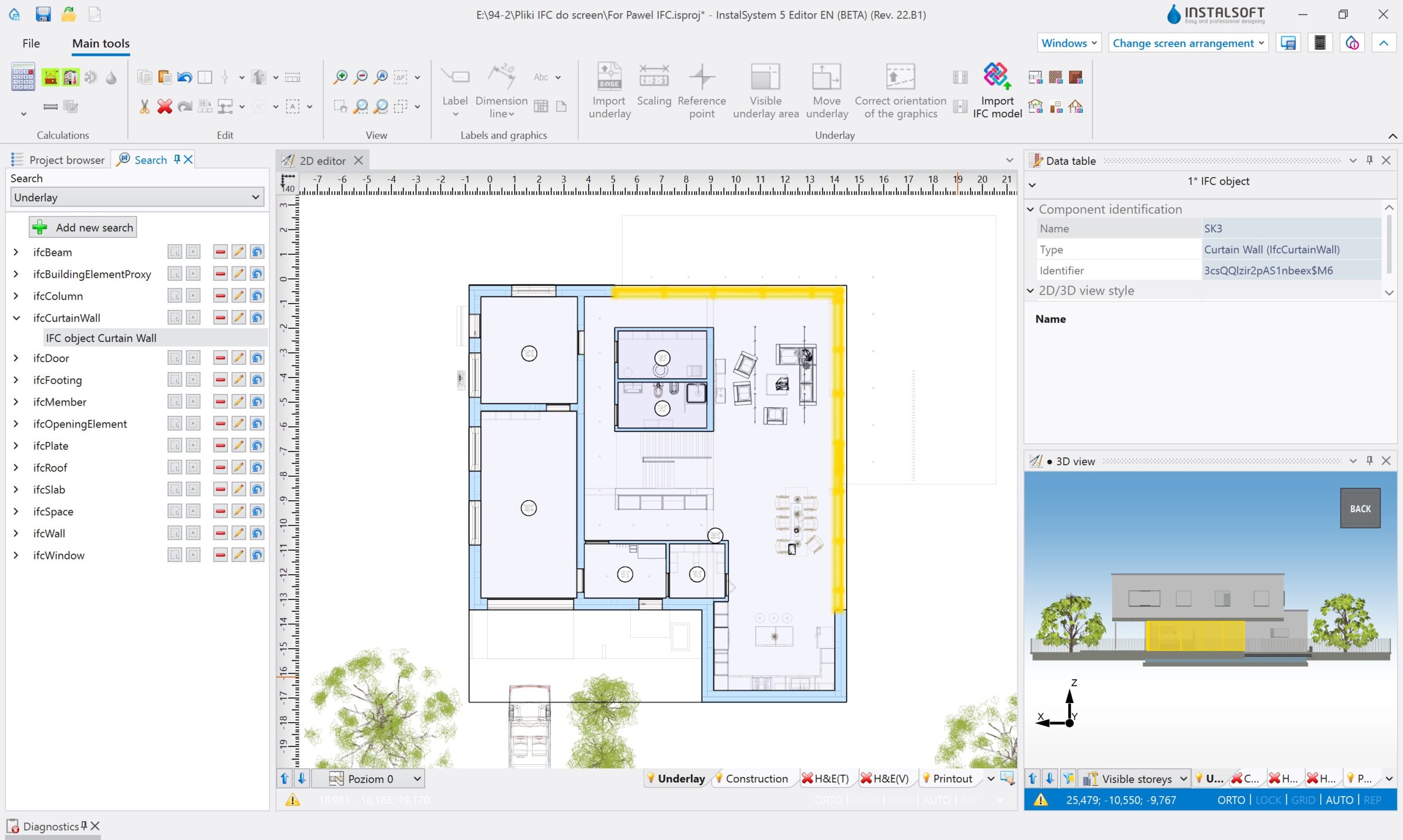
Tworzenie struktury budynku wymaganej do obliczeń cieplnych odbywa się w sposób graficzny na rzutach oraz w widoku 3D. Pakiet umożliwia pracę na podkładach wektorowych (typu PDF, DWG) oraz rastrowych (typu PDF, JPG, PNG). Alternatywnie wczytać można gotowy model budynku z formatu IFC (Industry Foundation Classes).
Rozwijająca się dynamicznie idea projektowania BIM otwiera nowe możliwości przyspieszenia i usprawnienia procesu projektowania budynków w wielu obszarach. Jednym z nich są obliczenia cieplne i ocena efektywności energetycznej budynku wraz z jego systemami wyposażenia technicznego. Ponadto pakiet posiada rozbudowaną bibliotekę materiałów budowlanych służących do definiowania warstw tworzących przegrody konstrukcyjne. Dzięki wielu narzędziom i funkcjom automatyzującym każdy z etapów realizacji projektu utworzenie kompletnego modelu cieplnego wraz z jego charakterystyką jest szybkie, łatwe i intuicyjne.
Moduły dostępne w EnergoSystem 5
Zobacz dostępną konfigurację i zawartość modułową w naszym cenniku!
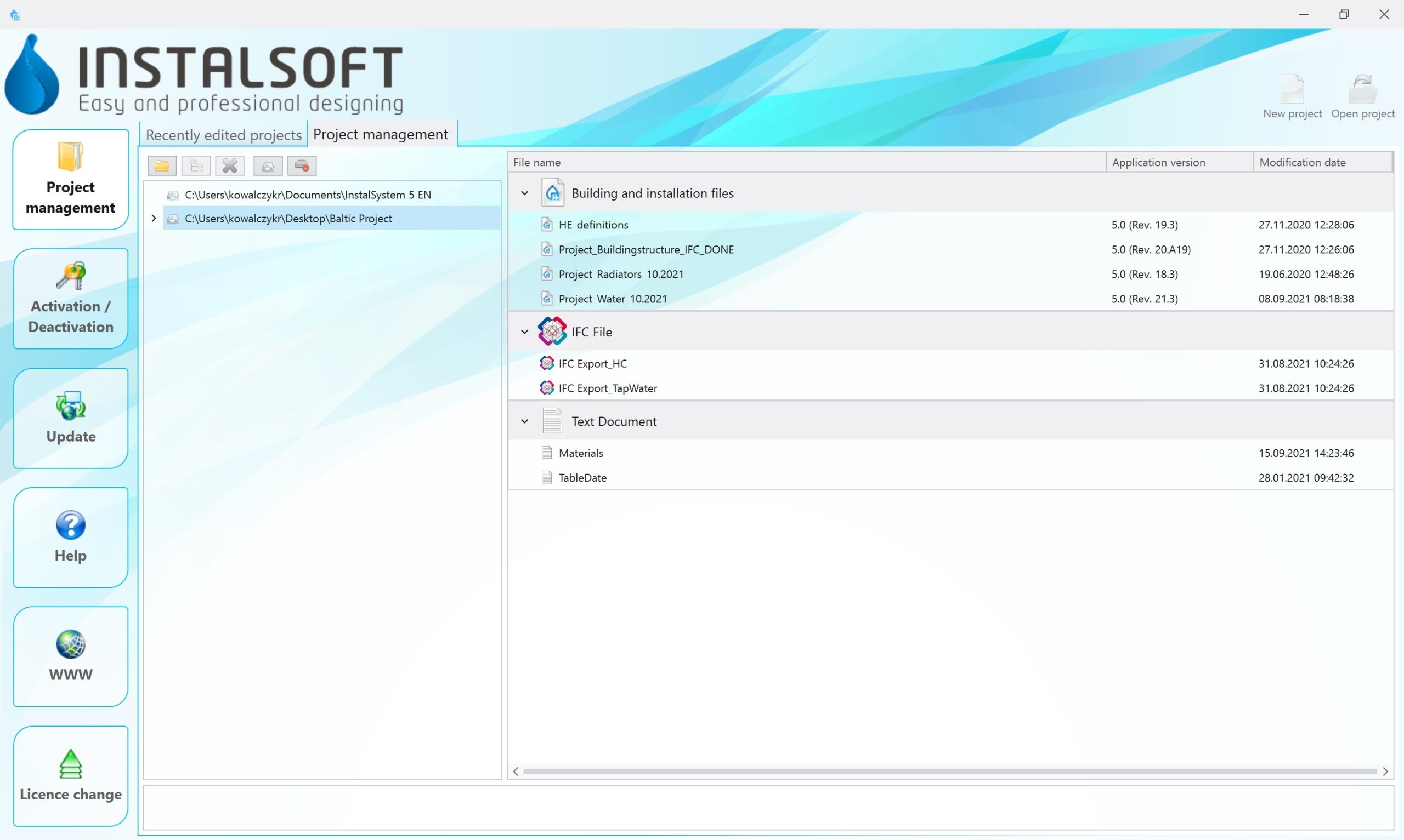
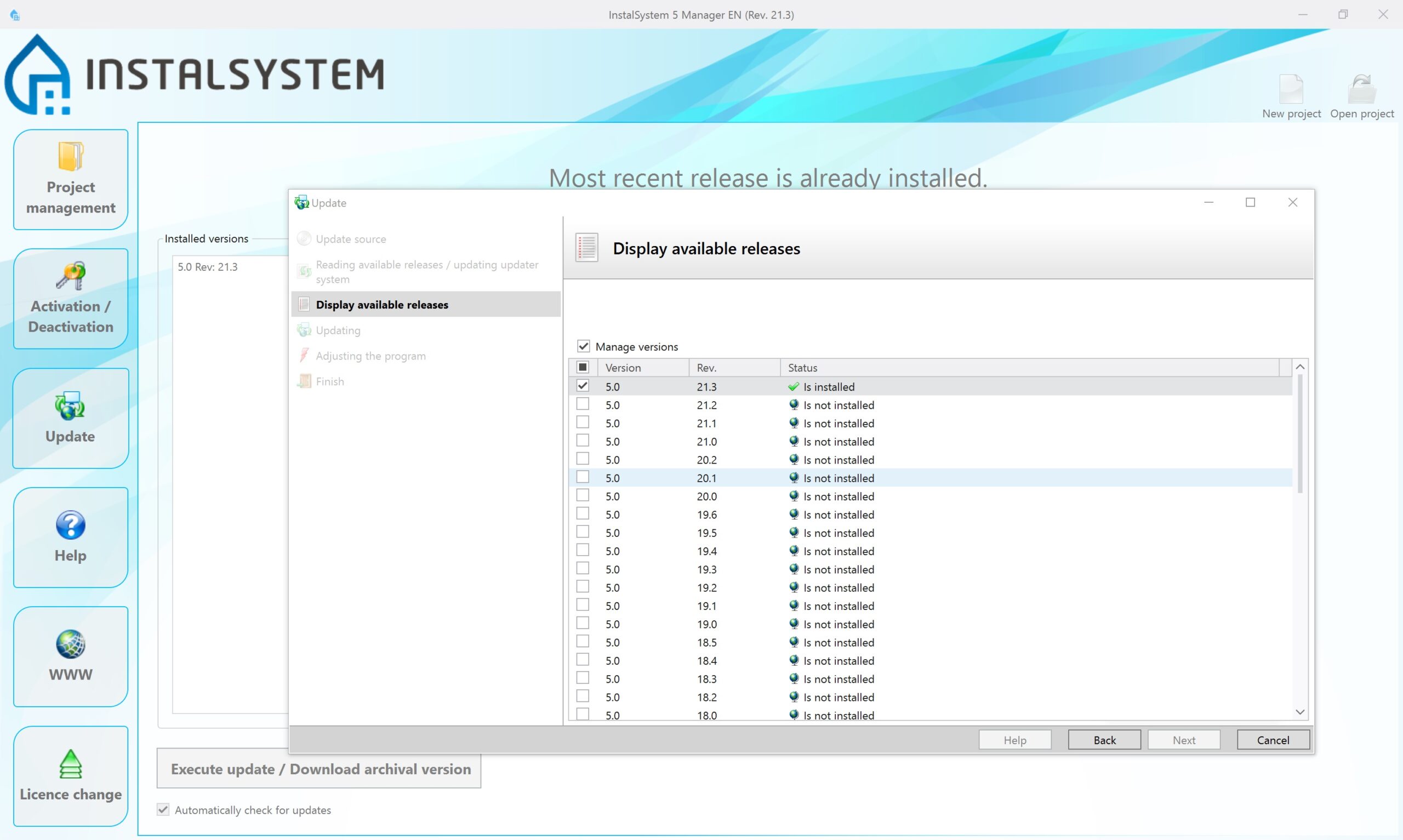
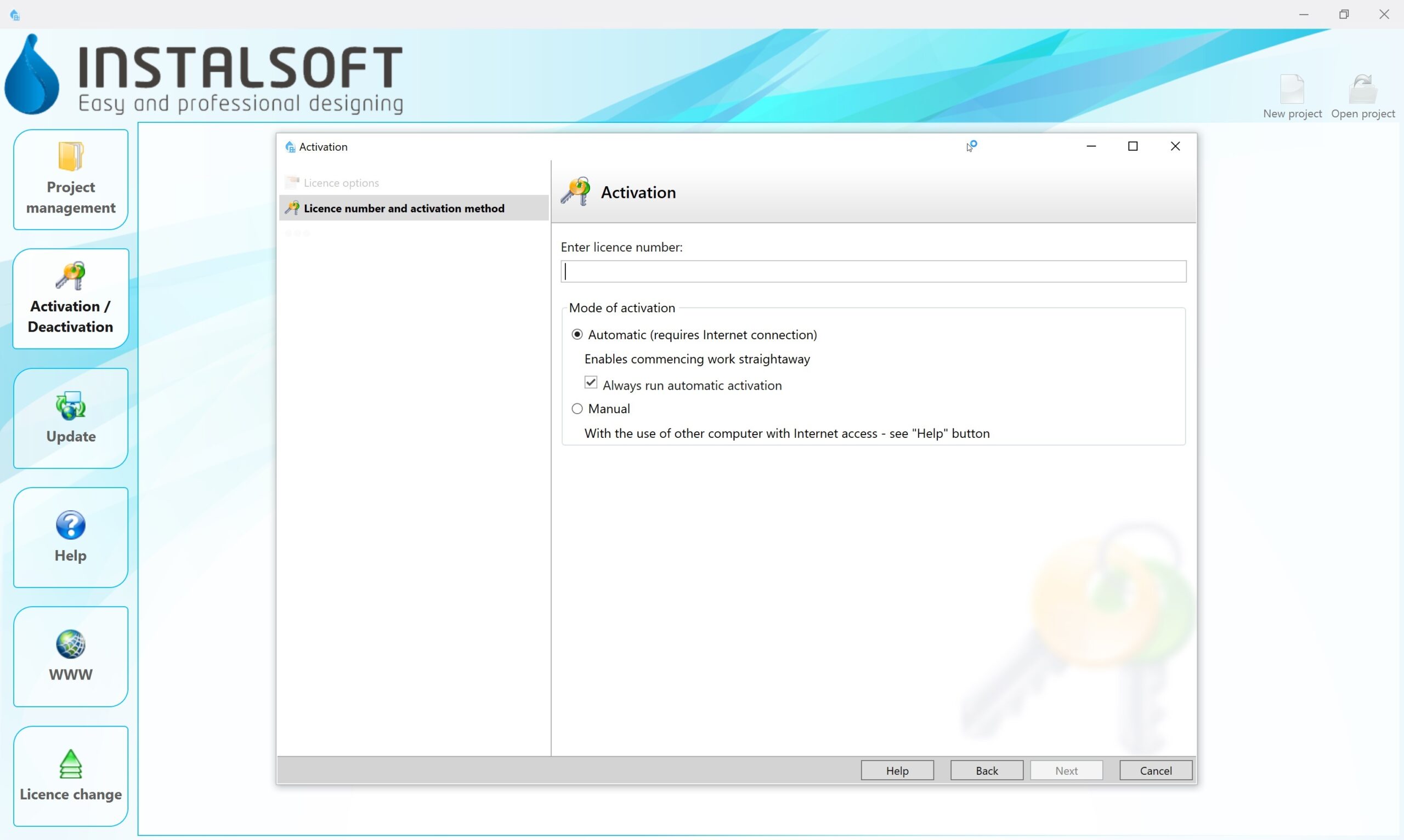
The ‘Base module’ is the basis for every InstalSystem 5 package configuration, as it contains all elements, functionalities and tools that create a common working environment for all designing and calculation modules. The user sees the ‘Base module’ as two separate programs / windows:
InstalSystem Manager with the following functionalities:
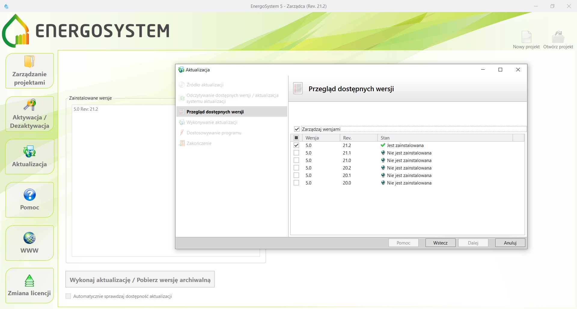
- Management of program activation and update as well as possibility of downloading older software package versions in order to process the already finished projects using the version upon which they have originally been prepared
- Control of the possessed package configuration (information on the modules available in the package, software upgrade possibilities)
- Management of projects (possibility of creating a new file project, opening an already existing project on a chosen program version, other operations regarding projects)
- Access to our HelpSystem support platform
- Possibility to report a problem encountered during work with the package directly to InstalSoft Support (Manager is equipped with a special form, the compilation of which facilitates report processing significantly)
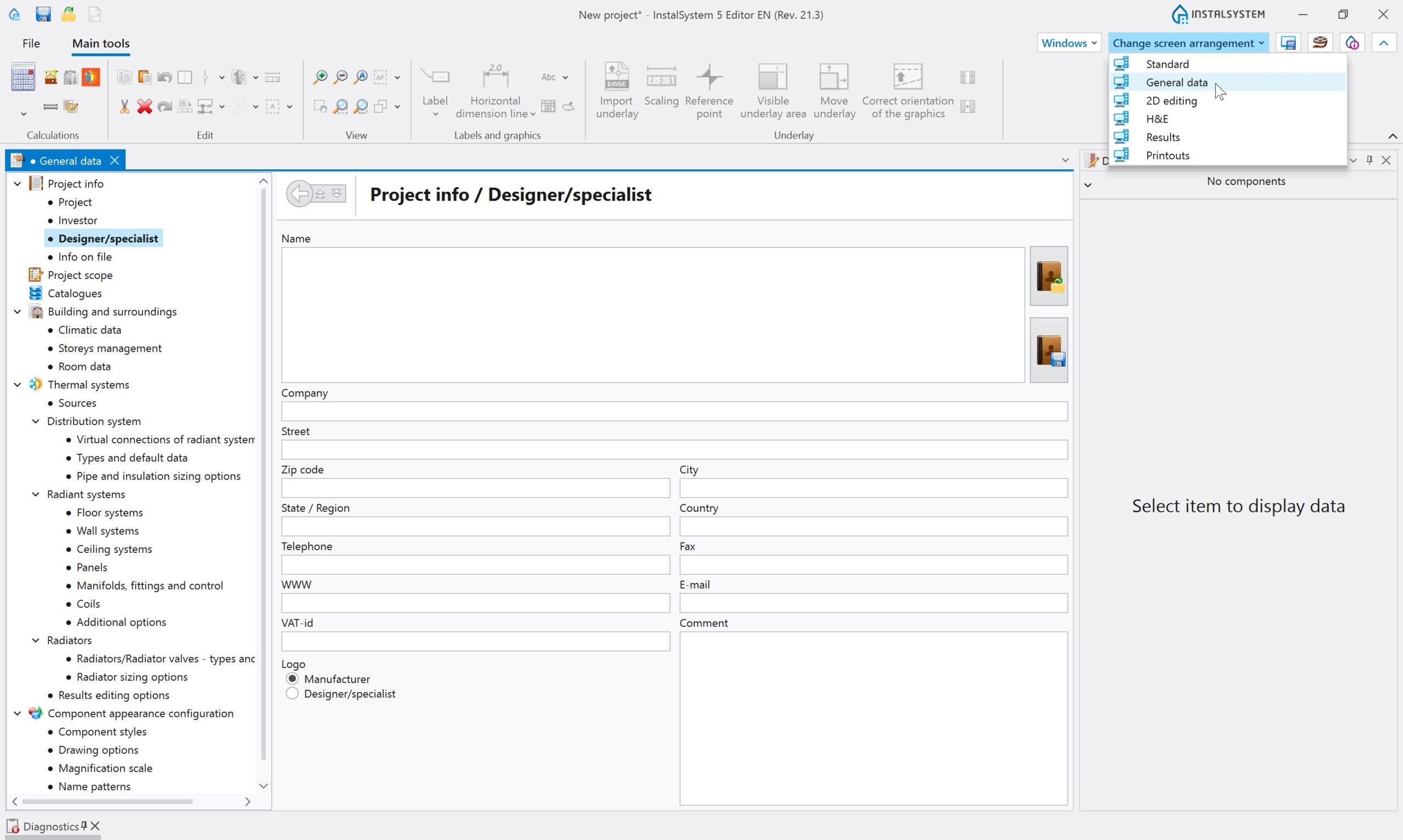
InstalSystem Editor, which is the main window for project preparation with the following functionalities:
- Possibility to elaborate many projects simultaneously (each is opened in a separate Editor window). While opening a new project, it is possible to use ready-made templates, that may contain various predefined settings adequate to a given project scope
- Control of the project scope. In regard to the defined project scope, some of Editor functions, icons and elements will be hidden in order to enhance user-friendliness
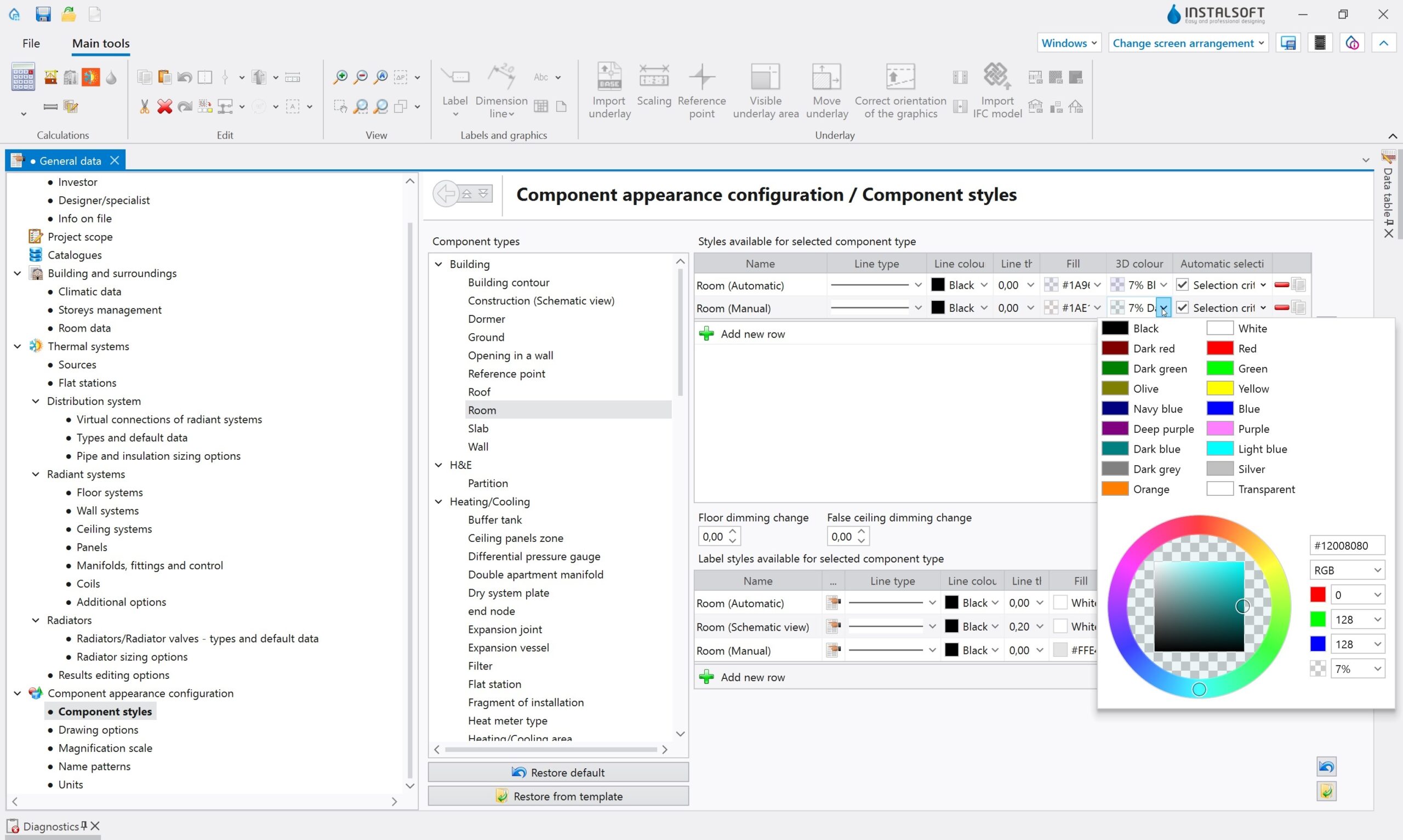
- General data and default data editing, as well as possibility of advanced editing of working screen and element layout
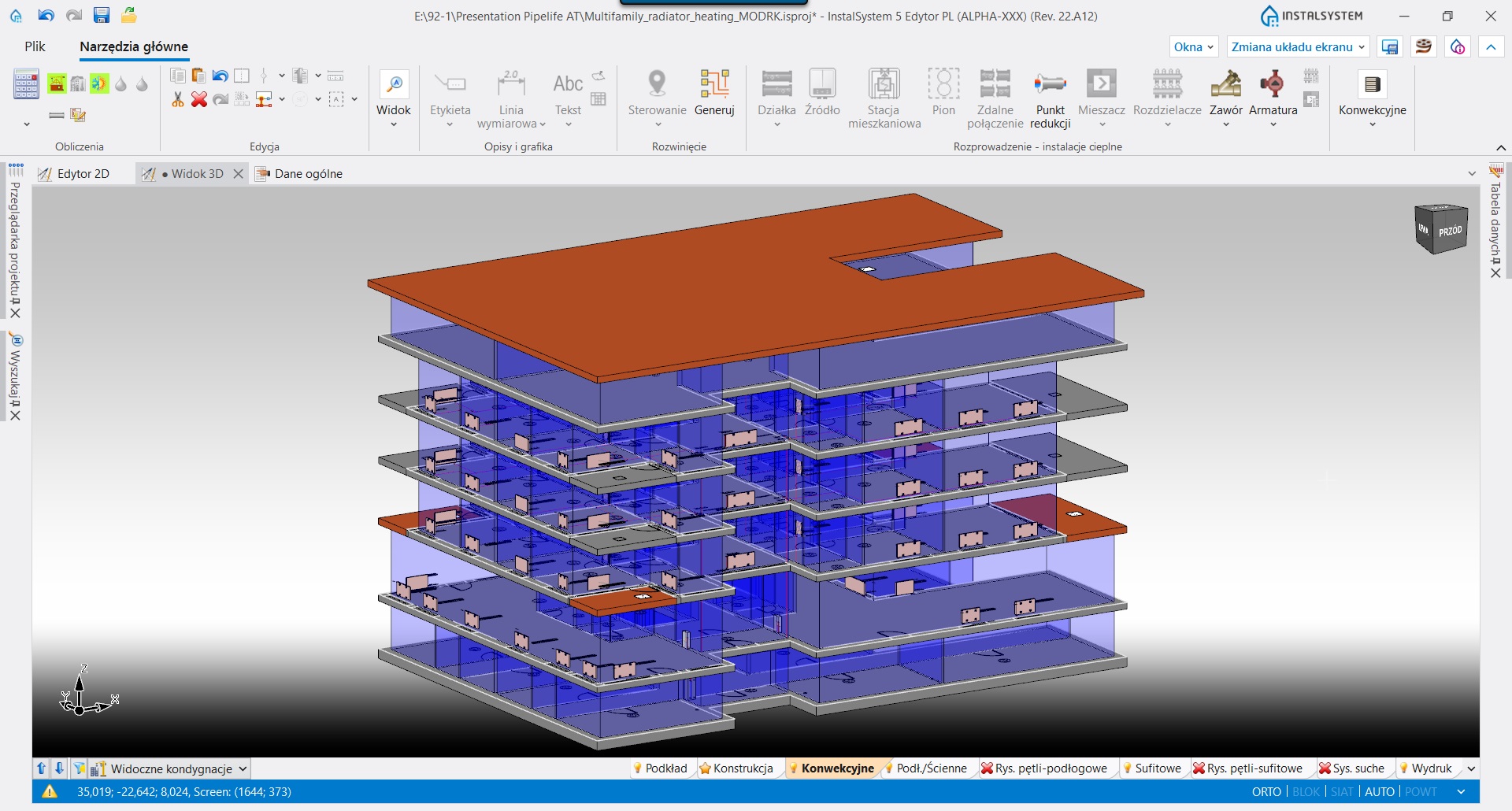
- 2D plan view project editing. Automatic generation of a 3D model, that allows to preview the project as well as to edit it to a certain extent
- Generation of plain schematic views for designed systems, their preview and modification
- Printout of drawings and of table results as well as possibility to define various layouts for graphic printouts, prepared for each project individually. Possibility to use one of many already-made predefined table results scope
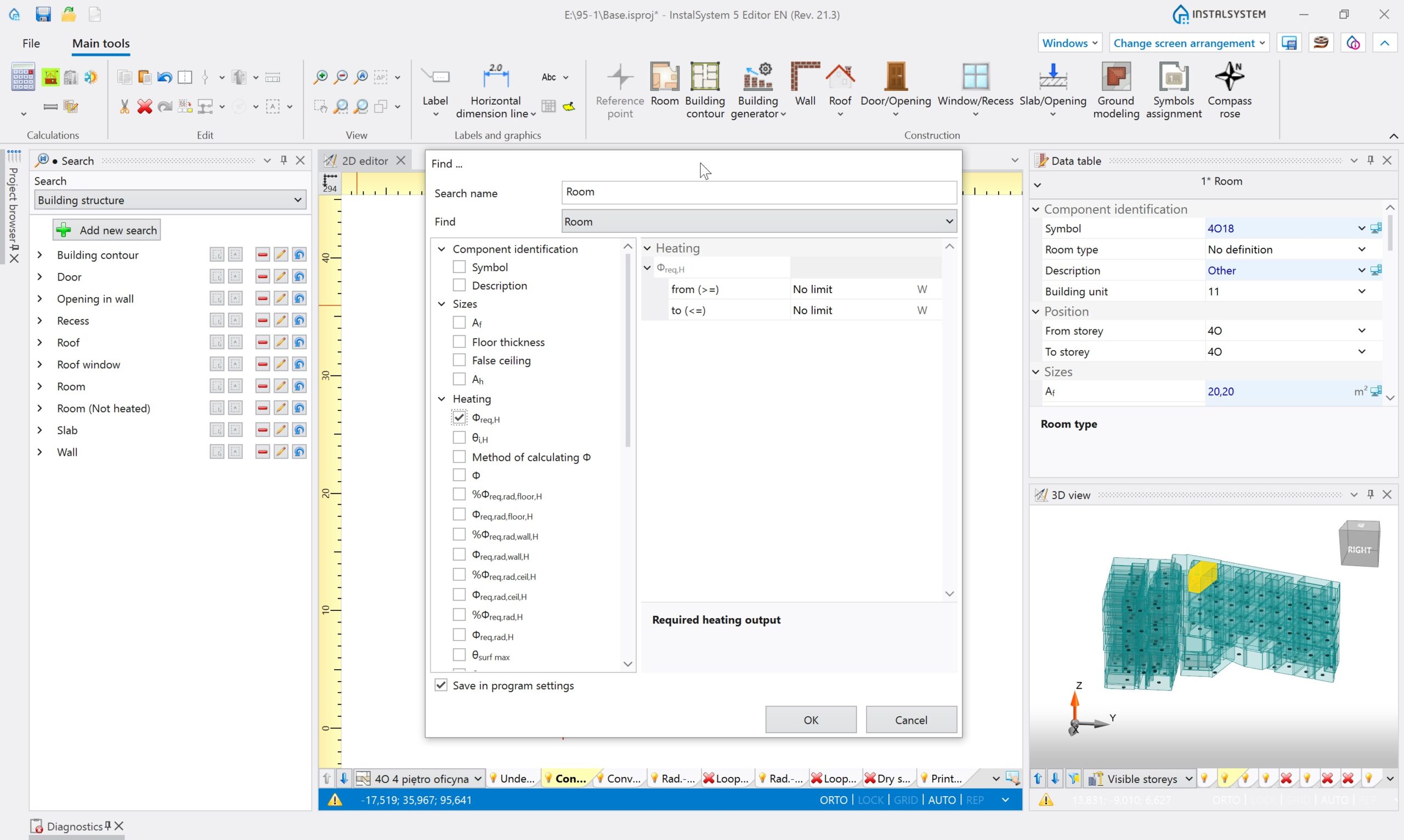
- Research of elements or of group of elements in a project according to various research criteria. The latter may be personalized. Researched / found elements are highlighted in all views and tables, thus making it easy to discover the same element in various places of the program
- Building structure editing – import and necessary modifications or graphic editing of the building structure providing basis for calculations and designing with use of other program modules. The building structure may be prepared in various scopes – as required by a given project – starting from simple room layout editing and finishing with a complete building structure comprising walls, ceilings, windows etc., allowing thus to perform full building heat loss calculations. Building structure editing is easier thanks to automated functions (automatic slab generation, wall generation on the basis of room outlines, possibility of declaring multi-storey walls and many others). Layout import of various formats (e.g. .dwg, .jpg, .PDF and others) may become the basis of building structure editing
- Working environment customization: it is possible to save various window layouts for Editor, that are dedicated for different activities of various modules or for different types of projects, and to switch between them during work with the program. InstalSystem 5 also introduces the possibility to work with Editor windows on two different displays, which is a very convenient and recommended solution
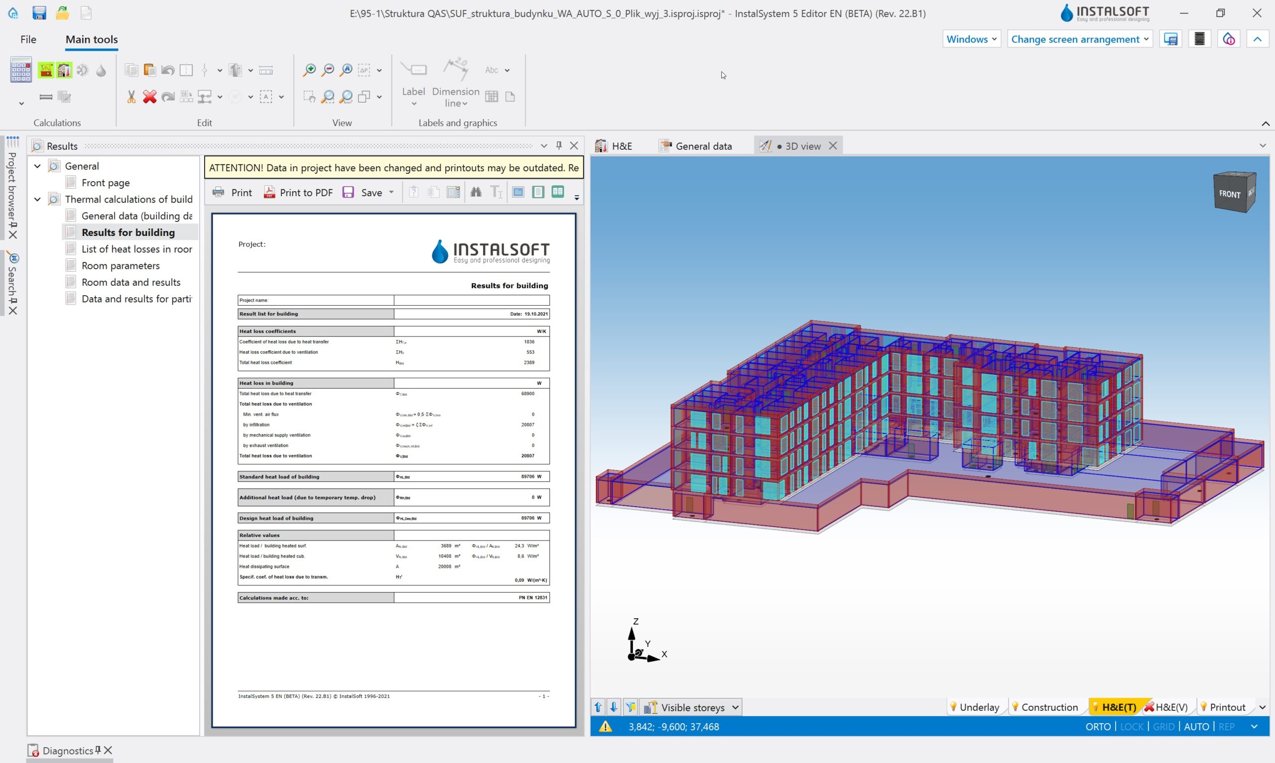
The ‘Heat loss’ module allows to calculate design heat loss for rooms and for a whole building. The results of such calculations may create a point of reference for a heating system design. Such calculations are performed according to one of the norms available in the package. Current information on this scope are available in:
Implementation of data for heat loss calculations is based on the graphical model of a building, whose edition is allowed by the °Base module°. Revolutionary automation solutions in terms of completing data for heat loss calculations render obtaining complete and detailed heat loss calculations much faster and easier.
Essential functionalities of the module:
- Calculations based on graphical elements, whose dimensions are automatically interpretated from the drawings / model
- Full 3D building model with advanced possibilities of indicating elements and view configuration
- Possibility to choose a calculation package norm to which printouts will be adjusted
- Automatic partition dimensioning according to the standards included in a chosen norm
- Easy declaration of most important building data in one place in the program. Information introduced in general data are propagated to building units and rooms
- User-friendly design navigation – advanced tool supporting design navigation and a browser of elements based on detailed criterion selection
- Automatic assignment of partition structure definitions to elements in the building, including the possibility to declare various default types and to declare criteria of their assignment to partitions of the same type, e.g. to external walls
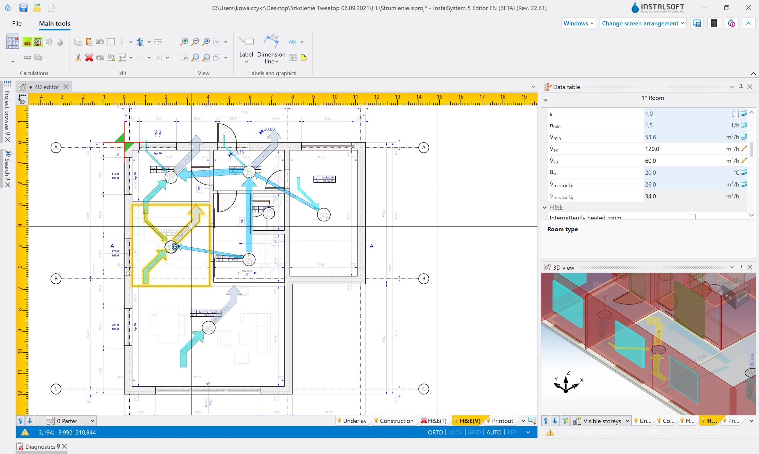
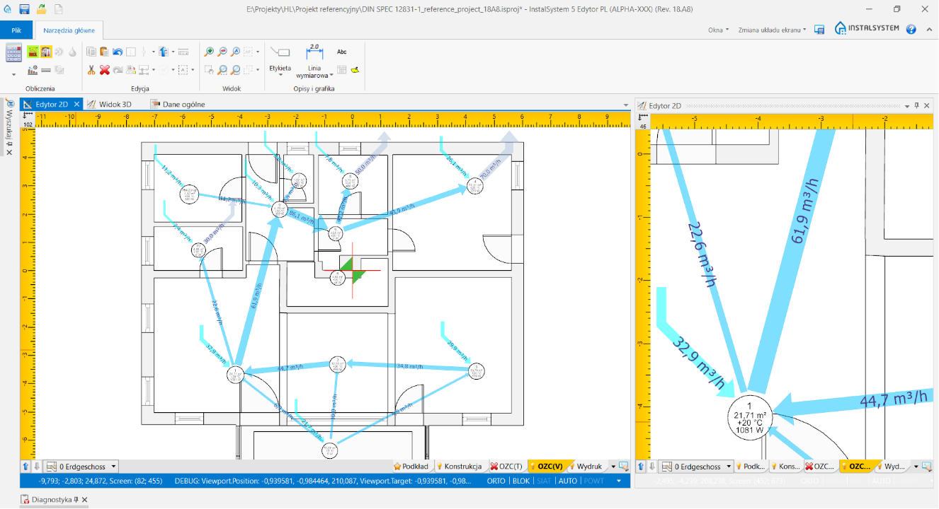
- Automatically generated graph of airflow in a building unit allowing to verify the ventilation airflow balance in a quick manner
- Possibility to control condensation
Energy certificates
(This module is available in Polish versions only)
In InstalSystem 5 there is available, implemented prototype data import from the gbXML (Green Building XML) format, which is part of the BIM technology. Import includes elements of the building structure: floors, rooms, walls with windows, doors and other openings.
Modul ‘IFC (BIM) import bazowy’ omogućuje uvoz različitih objekata klase IFC4 i IFC2x3 (iz područja konstrukcije, instalacija i ostalo), bez njihove interpretacije. Moguće je učitavanje više modela istovremeno. Objekti su vidljivi kako za 2D uređivač tako i za 3D prikaz. Upravljanje uvezenim modelom omogućava poseban Preglednik projekta i informacije vidljive u Tablici podataka. Objekti iz modela mogu se označavati ili skrivati. Također su vidljivi za funkciju SNAP prilikom uređivanja drugih područja u 2D uređivaču. Modeli (kao cjelina) mogu biti brisani ili ponovno uvoženi.
Modeli učitani korištenjem ovog modula mogu se interpretirati u pogledu građevinske konstrukcije zajedno s ‘IFC (BIM) interpretacija podataka o zgradi’. Samo geometrija modela može služiti kao pozadina za instalacije koje se projektuju u InstalSystemu 5, bez potrebe za interpretacijom. Rad s modelom također omogućuje otkrivanje sudara objekata prisutnih u IFC-u s objektima instalacija projektiranih u InstalSystemu 5. Modeli IFC-a podložni su izvozu u DXF/DWG i PDF formate.
Modul ‘IFC (BIM) interpretacija podataka o zgradi’ omogućuje visoko automatiziranu interpretaciju objekata iz područja građevinske strukture koji su uvezeni kao dio IFC modela. Interpretacija obuhvaća elemente kao što su: etaže (automatska ili poluautomatska interpretacija), zidovi (uključujući zidove s panelima), prozori, vrata i ostali otvori, krovovi, stropovi s otvorima (automatska interpretacija). Novost je automatska interpretacija prostorija iz ifcSpace objekata.
Rezultat interpretacije su odgovarajući objekti u paketu InstalSystem 5, stvarajući konstrukciju zgrade spremnu za daljnje uređivanje i proračune. Rezultantni objekti ne ovise o učitanom IFC modelu. To znači da konstrukcija zgrade dobivena na ovako visoko automatiziran način može biti korištena za daljnji projektantski rad u InstalSystemu 5 – izračun toplinskih opterećenja (toplinski opterećaj, projektirana energetska karakteristika) te kao osnova za projektiranje grijanih, rashladnih i sanitarnih instalacija u zgradi.
The ‘IFC (BIM) building structure elements export’ module enables the export of various IFC4 class objects in the field of building structure (horizontal/vertical partitions, sub-partitions and rooms along with their technical and calculation parameters).
The program exports construction projects designed in InstalSystem 5 to the IFC format, that entering the BIM path.
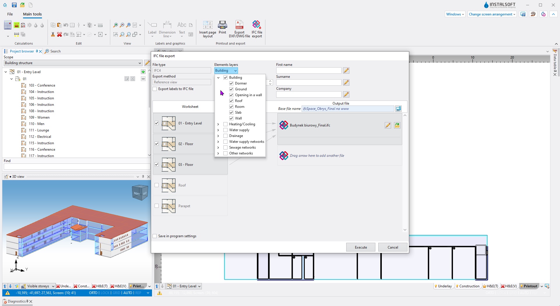
The building structure is exported based on the 3D model of the building and is part of the IFC Reference View export method defined by buildingSMART. The building export contains basic information about the name of objects and their properties, as well as an exact geometric representation of the objects.
Obejrzyj webinary i tutoriale
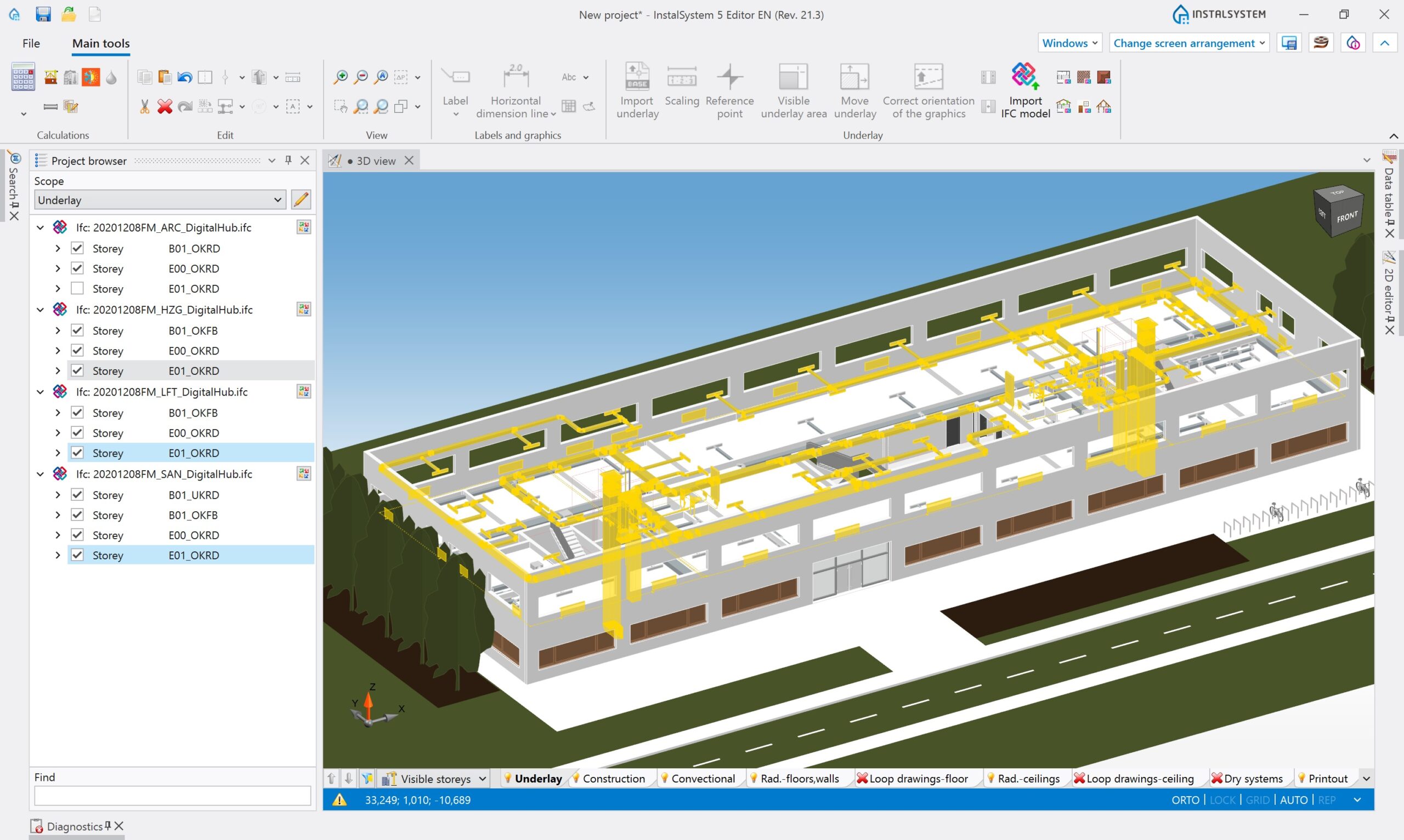
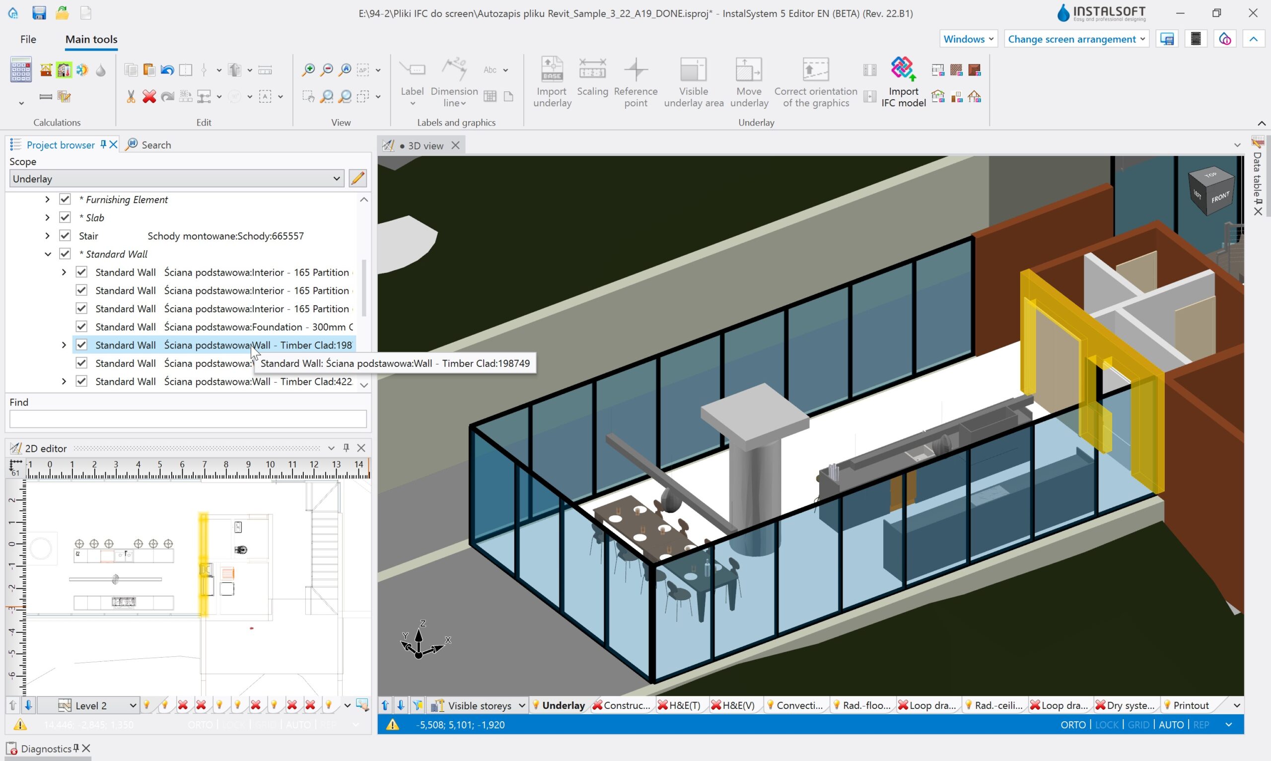
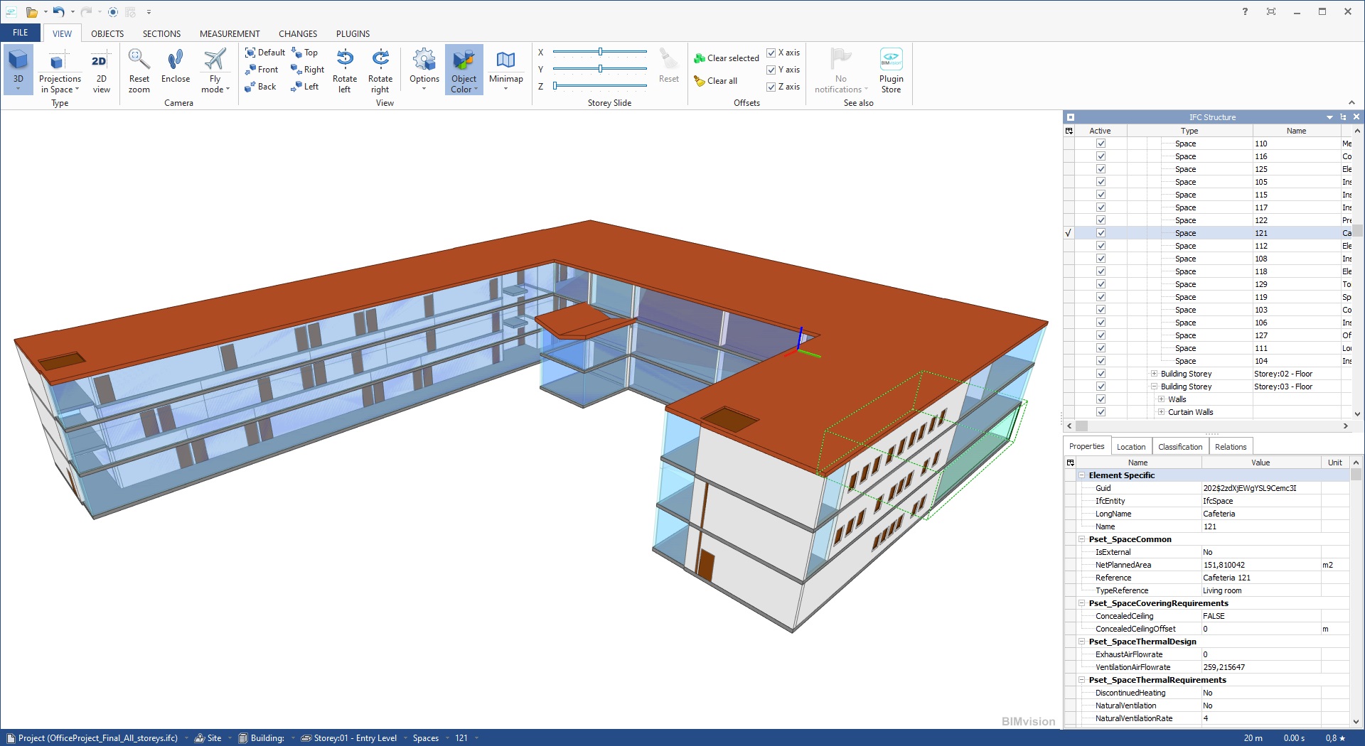
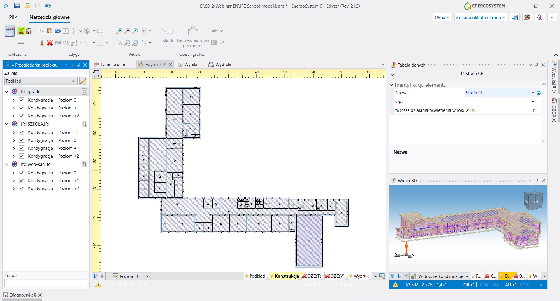
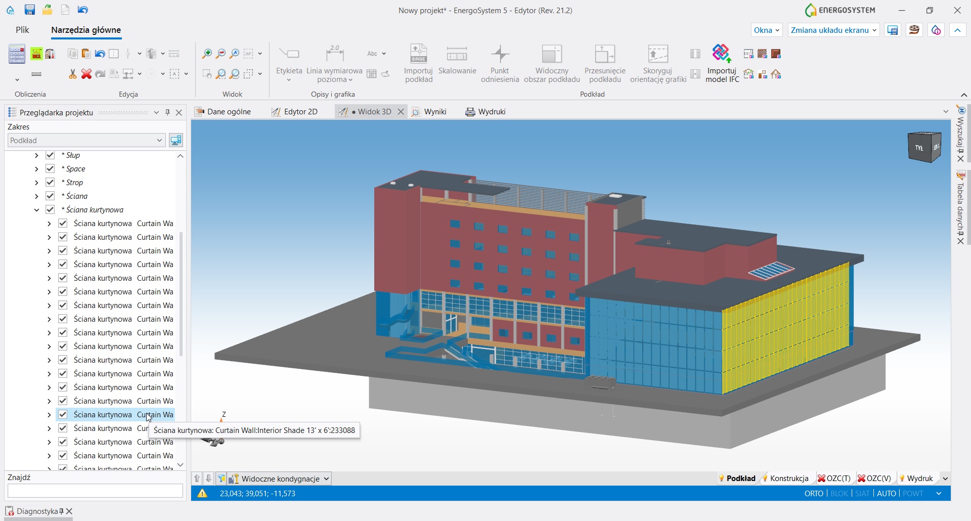
Pakiet EnergoSystem umożliwia import modelu budynku w formacie IFC, opracowanego wcześniej przez architekta w dedykowanym oprogramowaniu architektonicznym. Model architektoniczny budynku wraz z elementami wyposażenia i ew. systemami technicznymi widoczny jest zarówno na rzutach płaskich jak i na widoku 3D. Poprzez okno „Przeglądarka projektu” możliwa jest precyzyjna kontrola widoczności elementów na widokach 2D i 3D, a w razie zmian w modelu architektonicznym możliwy jest również ponowny import oraz łatwe i szybkie uwzględnienie zmian w modelu cieplnym budynku.
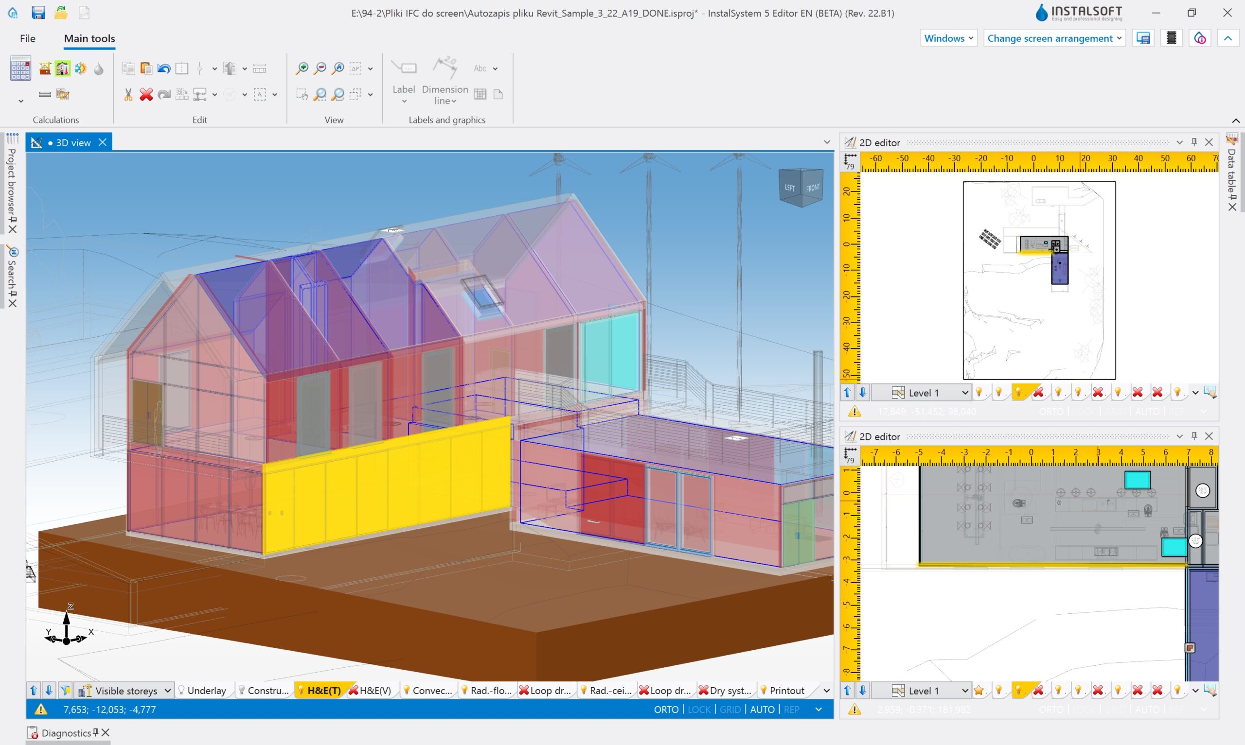
W pierwszym etapie przygotowania do obliczeń cieplnych budynku wykonywana jest interpretacja obiektów struktury budynku z pliku IFC (ścian, stropów, okien itp.) na analogiczne obiekty natywne pakietu EnergoSystem. Interpretacja wykonywana jest w sposób maksymalnie zautomatyzowany, dając jednocześnie projektantowi dużą kontrolę nad uzyskiwanym efektem. Co istotne, sam model budynku z IFC nie podlega modyfikacji, a tworzony jest równolegle model konstrukcyjny, który można modyfikować.
Na bazie utworzonego modelu konstrukcyjnego generowany jest automatycznie model cieplny budynku obejmujący wszystkie przegrody, przez które następuje wymiana ciepła (ściany zewnętrzne, stropy, ściany przy gruncie, ściany wewnętrzne itd.). Wymagane do obliczeń parametry cieplne przegród można określić definiując ich budowę warstwową, wybierając odpowiednie materiały z bazy danych lub wpisać ręcznie. Odpowiednie definicje przegród wraz z ich parametrami są przypisywane automatycznie właściwym przegrodom konstrukcyjnym. Efekt można zweryfikować w widoku 2D oraz 3D i w razie potrzeby skorygować.
Pakiet EnergoSystem umożliwia przeprowadzenie obliczeń projektowego obciążenia cieplnego w oparciu o normy: polską, europejską (bez krajowych załączników), niemiecką (DIN) oraz austriacką (ÖNORM). Planowane jest również rozszerzenie o normy rosyjskie (SNIP). Wraz z bogatą bazą danych klimatycznych kilkudziesięciu krajów otwiera to możliwość współuczestniczenia w projektowaniu budynków w inwestycjach wykonywanych poza granicami kraju.
Po wykonaniu obliczeń cieplnych możliwe jest sporządzenie świadectwa charakterystyki energetycznej budynku (dla obliczeń wg normy polskiej) oraz jego export do pliku XML celem zaimportowania do centralnego rejestru charakterystyk energetycznych. Interfejs programu bazujący na danych domyślnych umożliwia szybką analizę energetyczną wpływu różnych rozwiązań technicznych na uzyskiwane wartości współczynników przenikania ciepła U oraz wartość wskaźnika EP względem wartości referencyjnych (WT2017 lub WT2021).
Należy na końcu nadmienić, że zaprezentowana powyżej ścieżka modelowania budynku nie jest jedyną możliwą w pakiecie EnergoSystem. Posiadając rzuty poszczególnych kondygnacji w postaci plików DWG, DXF, PDF, PNG itp. możliwe jest również szybkie utworzenie kompletnej struktury budynku 3D z wykorzystaniem funkcji, które w sposób zautomatyzowany generują z rysunków wymagane elementy struktury budynku.
Ponadto pakiet EnergoSystem zgodny jest ze standardem InstalSystem co oznacza, że w tak utworzonym i zoptymalizowanym energetycznie projekcie budynku, możliwe jest następnie zaprojektowanie instalacji sanitarnych, wykorzystując do tego celu odpowiednie moduły obliczeniowe pakietu InstalSystem 5. Zaprojektowane instalacje można również eksportować do pliku IFC, uzupełniając tym samym cyfrowy model budynku i jego wyposażenia technicznego.
Pakiet EnergoSystem to produkt nowy, jednak bazujący na ponad 20 letnim doświadczeniu InstalSoft w zakresie obliczeń cieplnych budynków. Teraz to doświadczenie i wiodący na rynku poziom ergonomii i szybkości pracy, dzięki komunikacji BIM, stał się doskonałą opcją także dla architektów, audytorów i innych projektantów, którzy do tej pory nie korzystali z rozwiązań InstalSoft.
Poznaj zalety naszego oprogramowania
ULEPSZONA ERGONOMIA PRACY
Pakiet EnergoSystem 5 obfituje w mnogość funkcji i narzędzi poprawiających szybkość i komfort pracy. Niektóre są proste, inne bardziej rozbudowane, ale ich celem wspólnym było wyniesienie ergonomii pracy na wyższy poziom. Zobacz nasze wybrane narzędzia i funkcje.
Integracja modułów funkcjonalnych
Dzięki integracji wszystkich modułów funkcjonalnych w jednej aplikacji nie ma potrzeby uciążliwego przełączania się pomiędzy programami.
Dla zbudowania konstrukcji budynku lub obejrzenia wczytanej już instalacji z pliku IFC wystarczy przełączyć zakres edycji. Konfigurowalna widoczność poszczególnych zakresów edycji pozwala łatwo przewidzieć i usunąć kolizje.
Czytaj więcej…
Konfigurowalny interfejs użytkownika
Dzięki możliwości konfiguracji i zapisu wielu tzw. kompozycji ekranu możliwe jest optymalne rozplanowanie i rozmieszczenia okien programu.
Dla każdego z kolejnych etapów realizacji projektu, poprzez zapisanie, a następnie wybór z listy właściwej kompozycji, można szybko uzyskać aranżację, przy której praca jest najbardziej komfortowa i efektywna. Najczęściej wykorzystywanym funkcjom i narzędziom mogą być przypisywane skróty klawiaturowe. Podobnie zestaw funkcji widocznych po wciśnięciu prawego klawisza myszki jest w pełni konfigurowalny.
Czytaj więcej…
Dane ogólne i szablony projektów
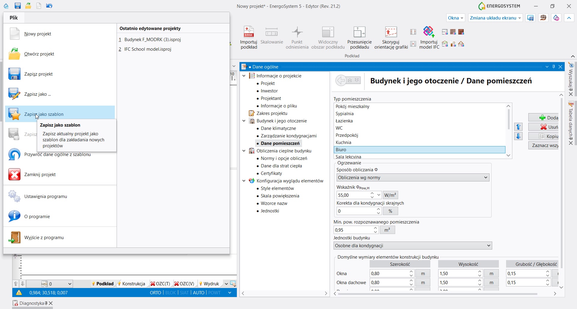
Zestaw standardowych danych dla projektu, opcjonalnie wraz z elementami graficznymi można zapisywać w postaci szablonów projektów.
Tym sposobem, po utworzeniu odpowiedniej liczby predefiniowanych szablonów typowych projektów, projektant unika konieczności wielokrotnego powtarzania tych samych czynności przygotowawczych przy pracy nad kolejnymi projektami. Dzięki systemowi dziedziczenia, dane ogólne są propagowane do elementów instalacji wprowadzonych w projekcie. Symbol “komputera” lub “ołówka” wyświetlany przy konkretnym polu danych informuje, czy wartość pochodzi z danych ogólnych czy została indywidualnie zmodyfikowana.
Czytaj więcej…
Interaktywne połączenie okien programu
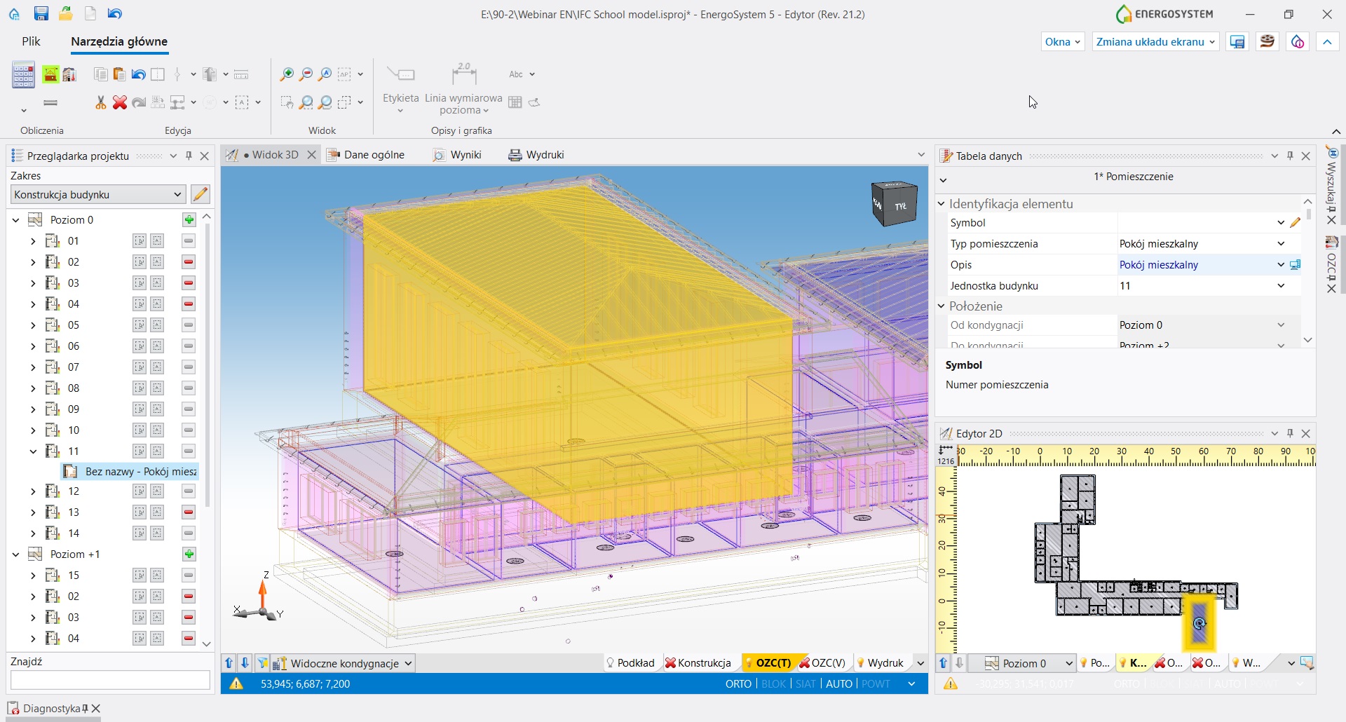
Interaktywne połączenie okien pozwala na szybkie znalezienie i podświetlenie wskazanego elementu we wszystkich aktywnych oknach programu.
Może się to odbyć przykładowo na rzucie, na widoku 3D lub w tabelach wyników. Dodatkowo po ustawieniu kursora myszy na danym elemencie wyświetlany jest tzw. hint z szczegółowymi informacjami technicznymi i parametrami. Ułatwia to analizę projektu, wyników obliczeń oraz znalezienie przyczyny zgłaszanych przez diagnostykę programu nieprawidłowości.
Czytaj więcej…
PODPOWIEDZI ROZWIĄZANIA TYPOWYCH PROBLEMÓW PROJEKTOWYCH
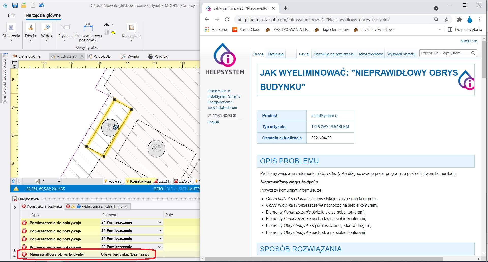
Dla diagnozowanych przez program częstych błędów i problemów projektowych podpięte są artykuły pomocy z platformy HelpSystem.
Zawierają one typowe przyczyny i podpowiedzi rozwiązania. Właściwy artykuł otwiera się automatycznie po kliknięciu w ikonkę z symbolem “?” przy danym komunikacie diagnostyki.
Czytaj więcej…
Łatwy i szybki dostęp do starszych wersji programu
W pierwszej fazie otwierania pliku projektu program rozpoznaje wersję, na której został on ostatnio zapisany.
Wybierając najnowszą lub starszą wersję programu, projektant ma kontrolę nad stanem samej aplikacji realizującej obliczenia.
Czytaj więcej…
64-bitowa architektura
Nowa generacja oprogramowania korzysta z pełnej – 64-bitowej architektury oraz z najnowocześniejszych silników graficznych.
Jak nigdy dotąd programy InstalSoft pozwalają na płynną pracę nawet przy bardzo dużych obiektach (ponad 100mb). Odpowiednia konfiguracja sprzętowa pozwoli nam na pracę przy najbardziej wymagających obiektach. Dotyczy to również obiektów pochodzących z procesu BIM. Przyspieszeniu uległo również wiele standardowych operacji edycyjnych i zoptymalizowany został czas obliczeń nawet o kilkadziesiąt procent.
Czytaj więcej…
AUTOMATYZACJA procesu projektowania
Dotąd niektóre etapy realizacji projektu, wymagane do uzyskania kompletnego modelu obliczeniowego i dokumentacji projektowej, były praco- i czasochłonne, a korekty modelu problematyczne. Dzięki wieloletniej współpracy z projektantami branżowymi oraz inwencji kadry inżynierskiej InstalSoft wiele z tych etapów udało się przyspieszyć i zautomatyzować. Poznaj nasze wybrane usprawnienia.
Model 3D budynku
Model 3D w pakiecie InstalSystem 5 tworzony jest automatycznie na podstawie rysunków rzutów płaskich oraz innych danych poszczególnych elementów.
Wiele dodatkowych narzędzi wspiera i przyspiesza budowanie modelu 3D, przykładowo: dane ogólne, możliwość kopiowania całych kondygnacji. Model 3D otwiera nas na współpracę w zakresie procesu BIM.
Czytaj więcej…
Tworzenie struktury budynku
Procedura tworzenia struktury budynku w pakiecie InstalSystem 5 przypomina realny proces tworzenia konstrukcji budynku, jest szybka i intuicyjna.
Po obrysowaniu pomieszczeń oraz konturu budynku i uruchomieniu funkcji “Automatyczne ściany, stropy i dachy”, wszystkie ściany, stropy międzykondygnacyjne, dachy i podłogi są generowane automatycznie. Dla tak wygenerowanej bryły budynku należy wstawić dach, okna i drzwi, tym samym uzyskując kompletną strukturę budynku. Umożliwiamy naszym projektantom wysoce zautomatyzowany proces uzyskania struktury budynku z plików IFC.
Czytaj więcej…
WYZNACZANIE OBCIąŻENIA CIEPLNEGO POMIESZCZEŃ I BUDYNKU
Na podstawie definicji przegrody cieplnej pakiet InstalSystem 5 automatycznie przypisuje parametry cieplne właściwym przegrodom rysunkowym.
Stropy międzykondygnacyjne dzielone są na osobne przegrody cieplne w sytuacji, gdy leżą nad kilkoma pomieszczeniami o potencjalnie różnej temperaturze wewnętrznej (analogicznie dzielony jest dach). W budynkach podpiwniczonych automatycznie rozpoznawana jest również część ściany leżąca poniżej gruntu, a nowa funkcja “Modelowanie gruntu’ pozwala na precyzyjne określenie ścian zewnętrznych w kontakcie z gruntem. Z kolei dla ułatwienia analizy przepływów powietrza wentylacyjnego tworzony jest bilans i diagram przepływów powietrza wentylacyjnego wraz z podaniem wartości strumieni powietrza.
Czytaj więcej…
NOWE OBSZARY ZASTOSOWANIA APLIKACJI
Ewolucja procesu projektowania która stanowią odpowiedź na coraz wyższe i bardziej zróżnicowane oczekiwania inwestorów i projektantów, zaowocowały nowymi modułami w pakiecie EnergoSystem 5.
Import BIM
Pakiet EnergoSystem 5 jest dostosowany do idei Open BIM. Umożliwiono pełne wsparcie dla importu plików w formacie IFC2x3 oraz IFC4.
Projektant może do programu wczytać dowolną ilość plików, może je usuwać lub zastępować co jest niezwykle istotne przy procesie BIM. Zarządzanie zaimportowanym modelem umożliwia dedykowana Przeglądarka projektu oraz informacje widoczne w Tabeli danych. Obiekty z modelu mogą być zaznaczane lub ukrywane. Są też widoczne dla funkcji SNAP przy edycji pozostałych zakresów w Edytor 2D. Modele wczytane z użyciem tego modułu mogą być interpretowane pod względem konstrukcji budynku, która może być w kolejnym kroku dowolnie modyfikowana.
Czytaj więcej…
Eksport BIM
Program eksportuje elementy struktury budynku, które powstały w EnergoSystem 5 do formatu IFC wpisując się tym samym w ścieżkę BIM.
Eksport konstrukcji jest wykonywany w oparciu o model 3D i wpisuje się w metodę eksportu typu IFC Reference View zdefiniowaną przez buildingSMART. Eksport zawiera podstawowe informacje o nazwie obiektów i ich właściwościach oraz dokładną reprezentację geometryczną obiektów. Nowe, dedykowane okno Eksport pliku IFC pozwala na eksport lub wyłączenie z eksportu etykiet elementów, precyzyjne ustalenie zakresu eksportowanych elementów czy wybór arkuszy podlegających eksportowi oraz ustalenie ilości wynikowych plików IFC. Eksport modeli IFC może odbywać się w sposób iteracyjny zgodnie z procesem BIM
Czytaj więcej…
Certyfikaty energetyczne
Możliwość sporządzenia świadectwa charakterystyki energetycznej dla budynków oraz szczegółowy wydruk projektowanej charakterystyki energetycznej budynku.
Moduł został rozbudowany m.in. o możliwość uwzględnienia instalacji chłodzenia oraz przycisk Eksport ŚChE (dostępny na wstążce w grupie Wydruk i eksport), który umożliwia eksport świadectwa charakterystyki energetycznej do pliku XML celem jego zaimportowania do centralnego rejestru charakterystyki energetycznej budynków. Program umożliwia pracę w oparciu zarówno o WT2017 oraz WT2021.
Czytaj więcej…
Technical support
We know how important is to support work of our Partners and Designers with such extensive software as InstalSystem 5.
Free help system in form of online articles
Tens hours of materials that show the program's possibilities step by step
Complex program of individual and group training in basic and advanced scope
Free support available 5 days a week
List of functionalities, tools and modules provided with each publication
Minimum and recommended hardware requirements for InstalSoft software
Current list of supported standards in InstalSoft packages
Do you have any questions? Do you need personalized offer? Contact with us!
