

InstalSystem 5 is an incredibly ergonomic MEP & HVAC tool for the designing and performing indoor heating, cooling and sanitary systems as well as heating load calculations.
Available modules in InstalSystem 5
See the available configurations options and theirs modules included in our price list!

The ‘Base module’ is the basis for every InstalSystem 5 package configuration, as it contains all elements, functionalities and tools that create a common working environment for all designing and calculation modules. The user sees the ‘Base module’ as two separate programs / windows:
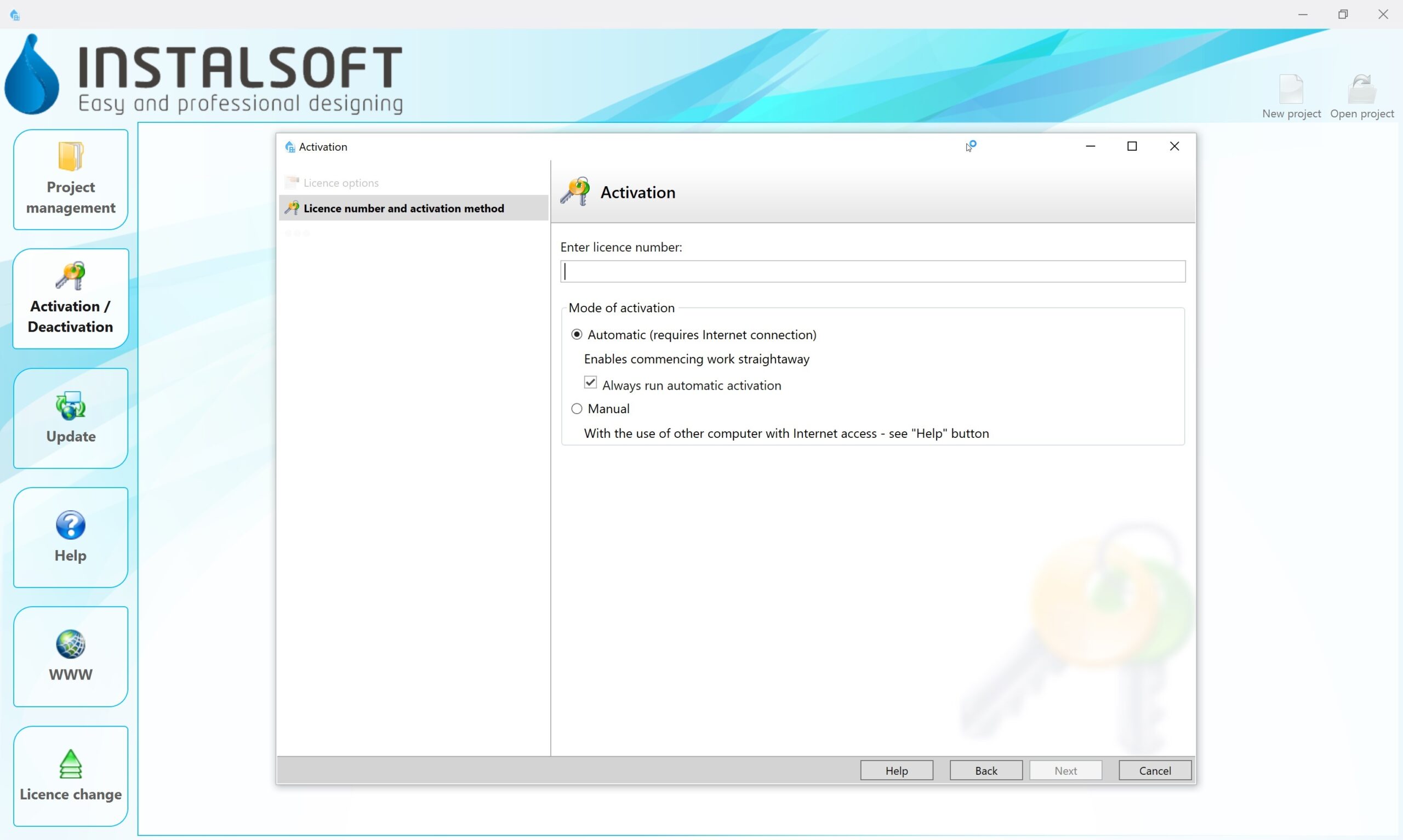
InstalSystem Manager with the following functionalities:
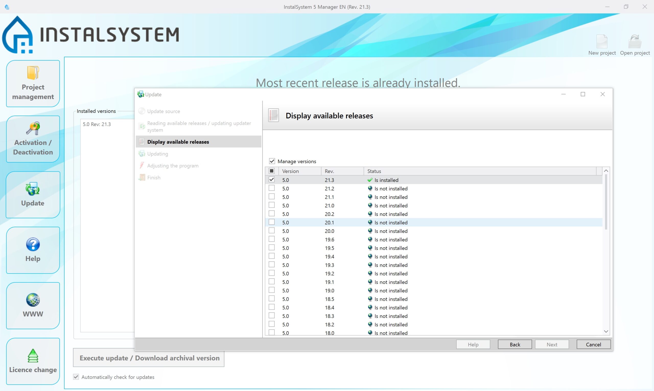
- Management of program activation and update as well as possibility of downloading older software package versions in order to process the already finished projects using the version upon which they have originally been prepared
- Control of the possessed package configuration (information on the modules available in the package, software upgrade possibilities)
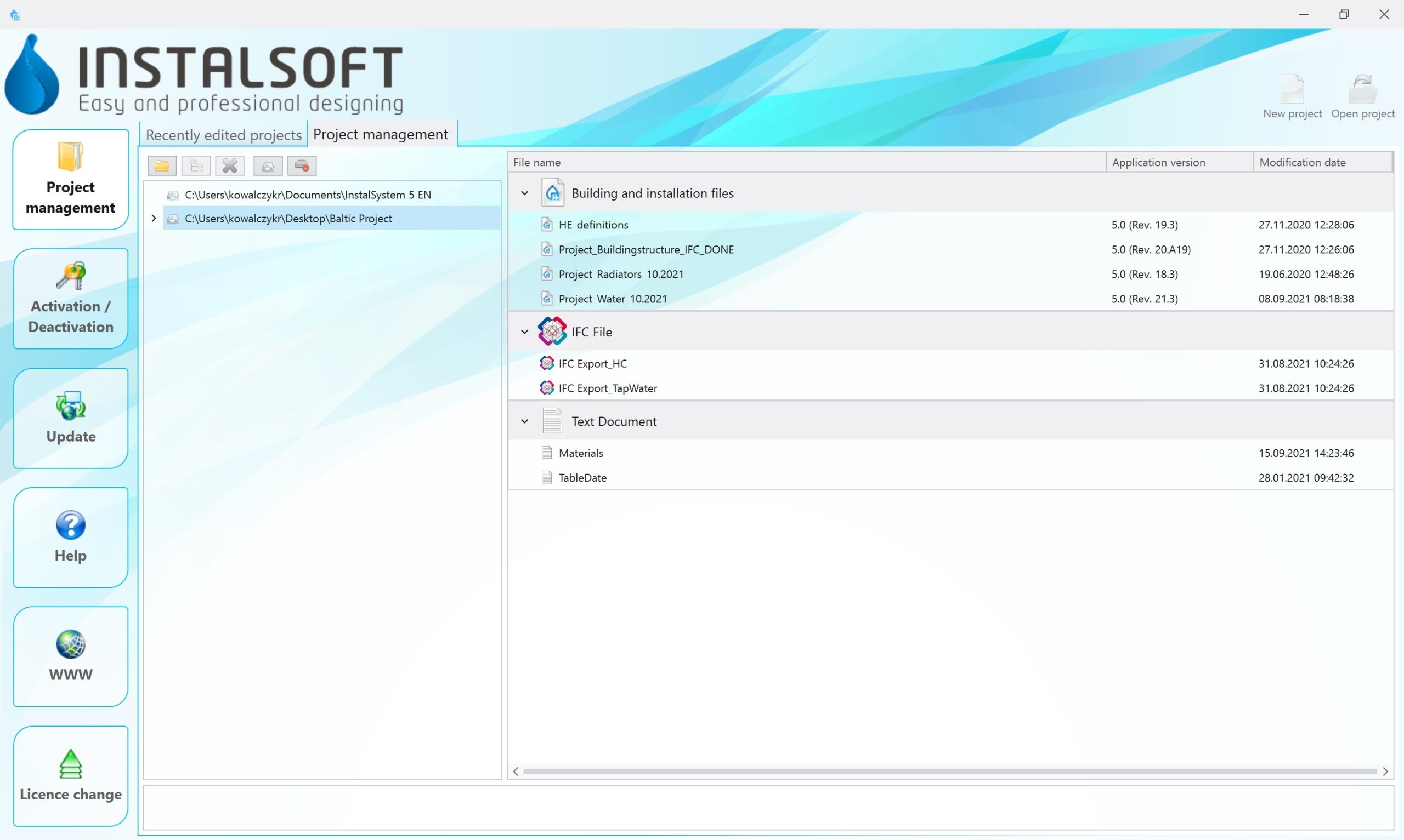
- Management of projects (possibility of creating a new file project, opening an already existing project on a chosen program version, other operations regarding projects)
- Access to our HelpSystem support platform
- Possibility to report a problem encountered during work with the package directly to InstalSoft Support (Manager is equipped with a special form, the compilation of which facilitates report processing significantly)
InstalSystem Editor, which is the main window for project preparation with the following functionalities:
- Possibility to elaborate many projects simultaneously (each is opened in a separate Editor window). While opening a new project, it is possible to use ready-made templates, that may contain various predefined settings adequate to a given project scope
- Control of the project scope. In regard to the defined project scope, some of Editor functions, icons and elements will be hidden in order to enhance user-friendliness
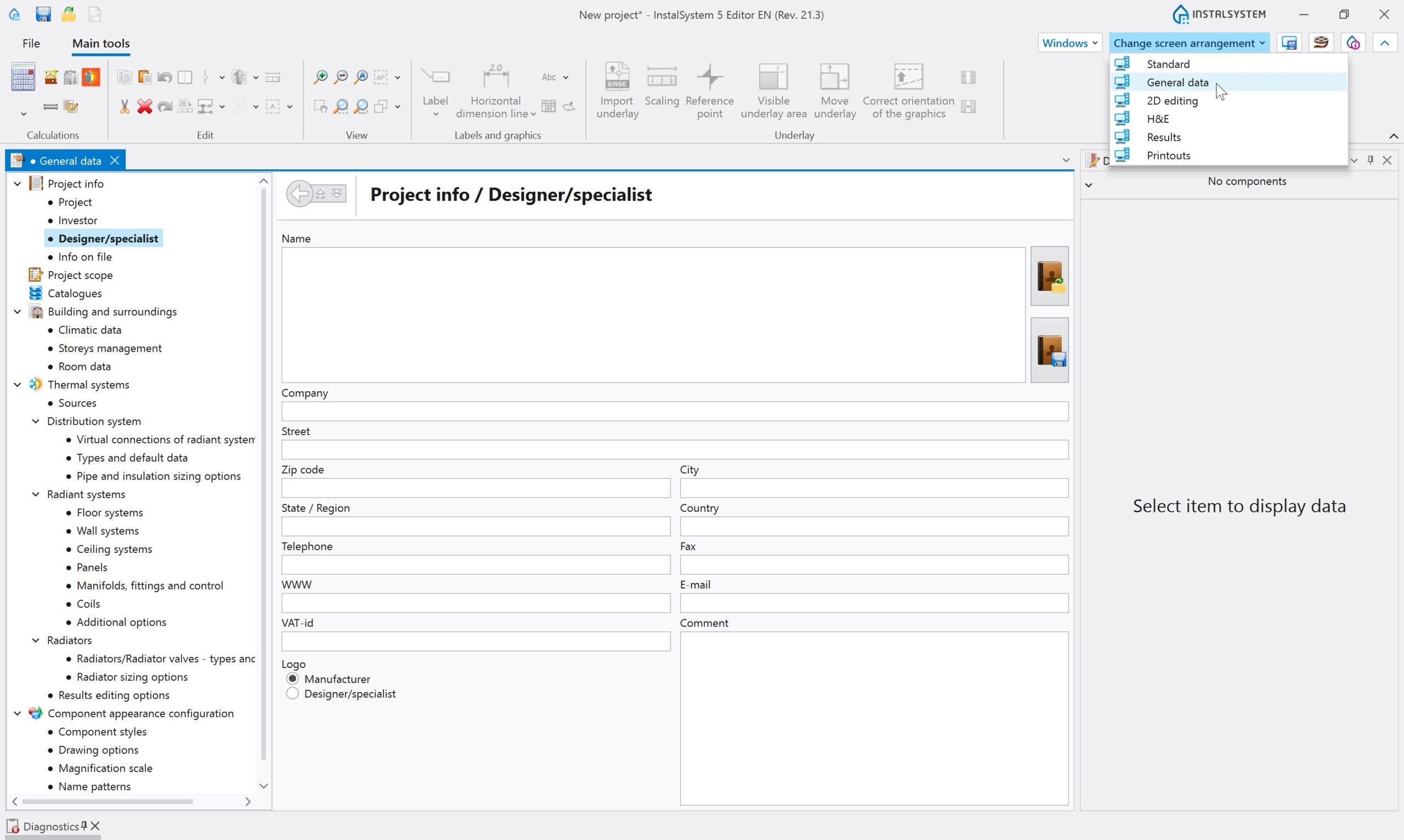
- General data and default data editing, as well as possibility of advanced editing of working screen and element layout
- 2D plan view project editing. Automatic generation of a 3D model, that allows to preview the project as well as to edit it to a certain extent
- Generation of plain schematic views for designed systems, their preview and modification
- Printout of drawings and of table results as well as possibility to define various layouts for graphic printouts, prepared for each project individually. Possibility to use one of many already-made predefined table results scope
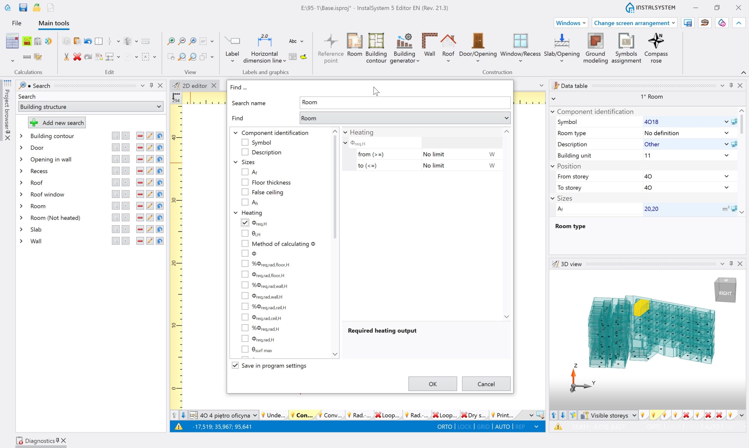
- Research of elements or of group of elements in a project according to various research criteria. The latter may be personalized. Researched / found elements are highlighted in all views and tables, thus making it easy to discover the same element in various places of the program
- Building structure editing – import and necessary modifications or graphic editing of the building structure providing basis for calculations and designing with use of other program modules. The building structure may be prepared in various scopes – as required by a given project – starting from simple room layout editing and finishing with a complete building structure comprising walls, ceilings, windows etc., allowing thus to perform full building heat loss calculations. Building structure editing is easier thanks to automated functions (automatic slab generation, wall generation on the basis of room outlines, possibility of declaring multi-storey walls and many others). Layout import of various formats (e.g. .dwg, .jpg, .PDF and others) may become the basis of building structure editing
- Working environment customization: it is possible to save various window layouts for Editor, that are dedicated for different activities of various modules or for different types of projects, and to switch between them during work with the program. InstalSystem 5 also introduces the possibility to work with Editor windows on two different displays, which is a very convenient and recommended solution

The ‘Heat loss’ module allows to calculate design heat loss for rooms and for a whole building. The results of such calculations may create a point of reference for a heating system design. Such calculations are performed according to one of the norms available in the package. Current information on this scope are available in:
Implementation of data for heat loss calculations is based on the graphical model of a building, whose edition is allowed by the °Base module°. Revolutionary automation solutions in terms of completing data for heat loss calculations render obtaining complete and detailed heat loss calculations much faster and easier.
Essential functionalities of the module:
- Calculations based on graphical elements, whose dimensions are automatically interpretated from the drawings / model
- Full 3D building model with advanced possibilities of indicating elements and view configuration
- Possibility to choose a calculation package norm to which printouts will be adjusted
- Automatic partition dimensioning according to the standards included in a chosen norm
- Easy declaration of most important building data in one place in the program. Information introduced in general data are propagated to building units and rooms
- User-friendly design navigation – advanced tool supporting design navigation and a browser of elements based on detailed criterion selection
- Automatic assignment of partition structure definitions to elements in the building, including the possibility to declare various default types and to declare criteria of their assignment to partitions of the same type, e.g. to external walls
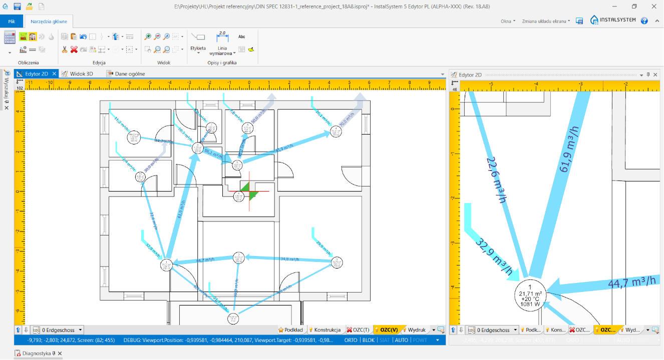
- Automatically generated graph of airflow in a building unit allowing to verify the ventilation airflow balance in a quick manner
- Possibility to control condensation


The module enables:
- Editing in the project (inserting and data edition)
- Sizing
- Hydraulic calculations
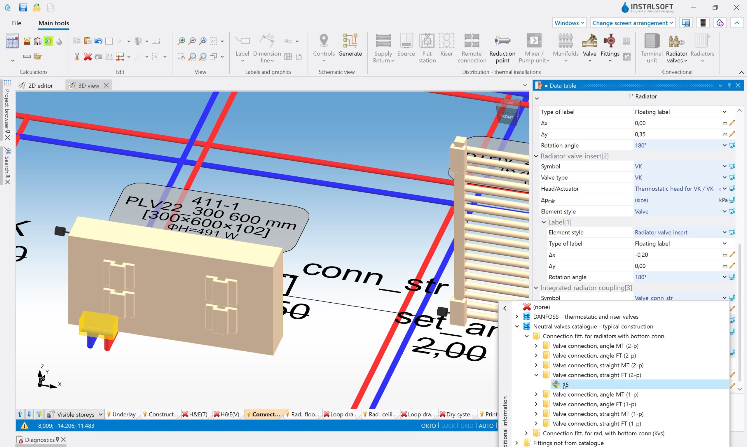
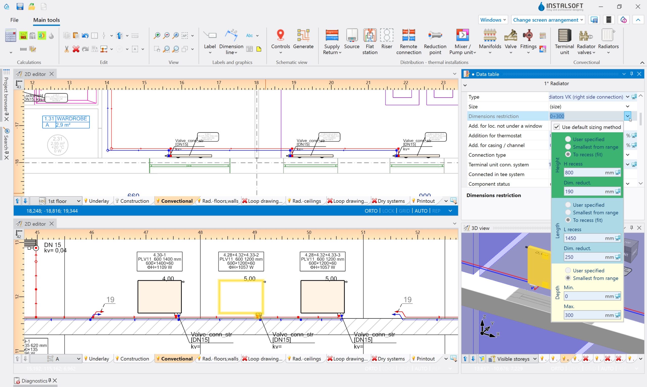
- Listing in a bill of materials of convective radiators – from catalogs (neutral or company) or not from catalogs, as well as fittings integrated with them (‘subordinate elements’)
The entire installation is calculated in accordance with the ‘Heating systems’ module (two-pipe installations only).
Module uses installation data and (not obligatorily) building structure, entered graphically in a specialized editor, and in cooperating modules.


Radiant systems
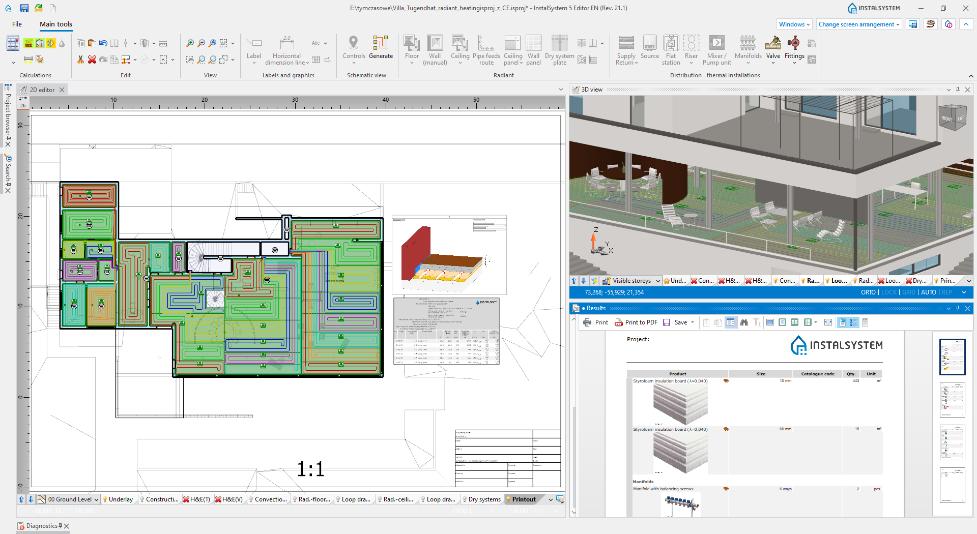
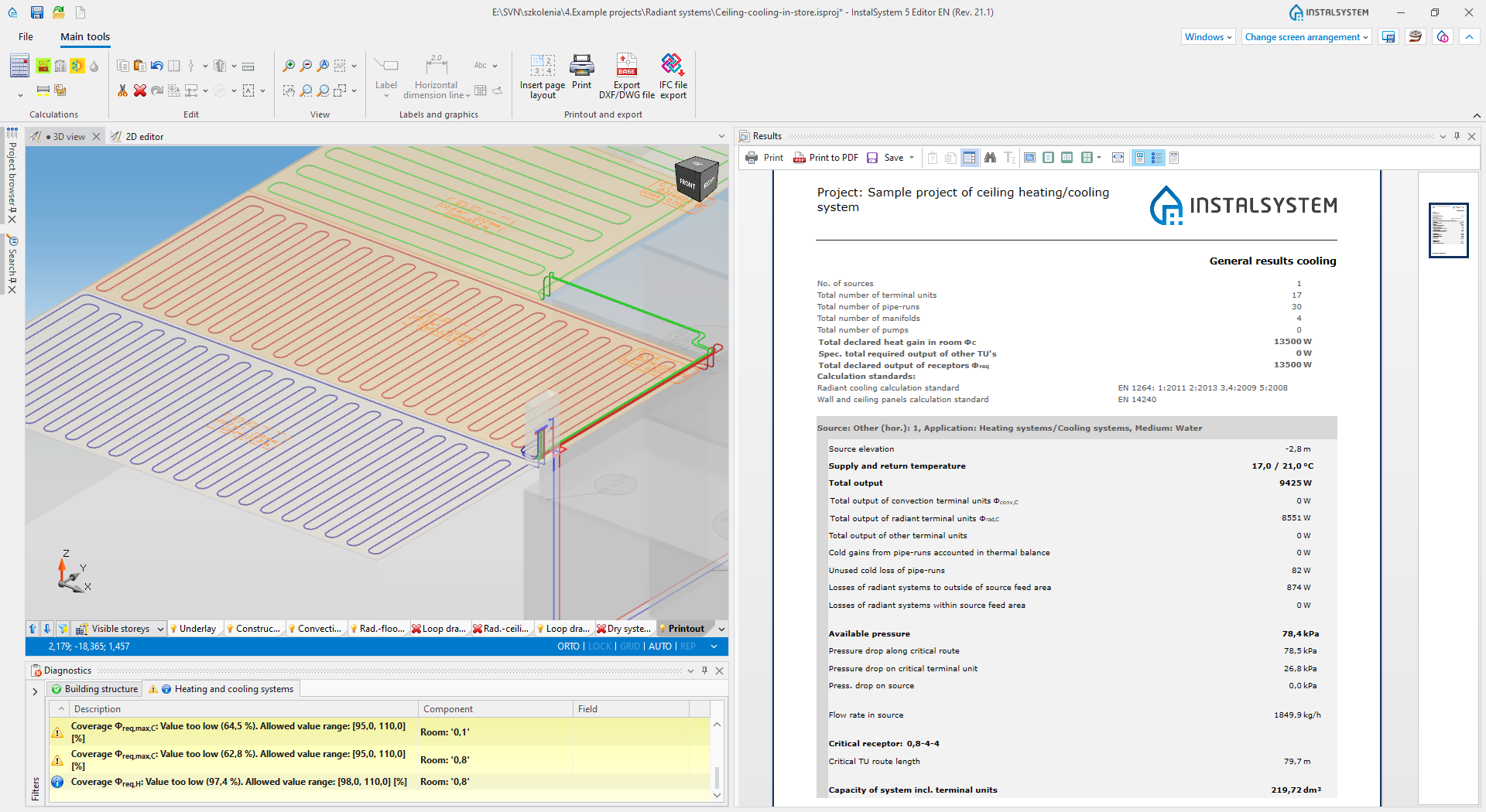
The module enables design of radiant heating and cooling systems (floor – including also those with return temp. limiter, wall, ceiling) based on pipes arranged freely in a screed or laid in dry boards (not modular nor panel solutions). It covers traditional wet system in the whole scope, and dry systems in the common scope – particular functionalities of the latter are covered by the ‘Dry system boards arrangement’ module.
Depending on the availability of the ‘Heating systems’ module and/or the ‘Cooling systems’ module in the configuration, we have the following possibilities:
‘Heating systems’ – heating calculation + checking cooling output of the system sized to cover heating demand
‘Cooling systems’ – cooling calculations (without possibility to check heating output)
‘Heating systems’ and ‘Cooling systems’ – sum of the above
The module uses the installation and building data entered graphically in a specialized editor, and in cooperating modules. Calculations are made in accordance with the standards listed below.
- Scope of calculations:
- Calculation of thermal output
- Hydraulic calculations
- Sizing / checking the correctness of geometric parameters (layer thicknesses)
- Sizing / control of pipe laying spacings
- Hydraulic balancing
- Sizing and hydraulic calculations of manifold accessories
- Visual presentation, including laying loops and connections
- Standards and rules on which the calculations are made
- List of standards and methods used for sizing and calculations
- Limitations:
- Inability to supply systems in one room from different sources

The ‘Base module’ is the basis for every InstalSystem 5 package configuration, as it contains all elements, functionalities and tools that create a common working environment for all designing and calculation modules. The user sees the ‘Base module’ as two separate programs / windows:
InstalSystem Manager with the following functionalities:
- Management of program activation and update as well as possibility of downloading older software package versions in order to process the already finished projects using the version upon which they have originally been prepared
- Control of the possessed package configuration (information on the modules available in the package, software upgrade possibilities)
- Management of projects (possibility of creating a new file project, opening an already existing project on a chosen program version, other operations regarding projects)
- Access to our HelpSystem support platform
- Possibility to report a problem encountered during work with the package directly to InstalSoft Support (Manager is equipped with a special form, the compilation of which facilitates report processing significantly)
InstalSystem Editor, which is the main window for project preparation with the following functionalities:
- Possibility to elaborate many projects simultaneously (each is opened in a separate Editor window). While opening a new project, it is possible to use ready-made templates, that may contain various predefined settings adequate to a given project scope
- Control of the project scope. In regard to the defined project scope, some of Editor functions, icons and elements will be hidden in order to enhance user-friendliness
- General data and default data editing, as well as possibility of advanced editing of working screen and element layout
- 2D plan view project editing. Automatic generation of a 3D model, that allows to preview the project as well as to edit it to a certain extent
- Generation of plain schematic views for designed systems, their preview and modification
- Printout of drawings and of table results as well as possibility to define various layouts for graphic printouts, prepared for each project individually. Possibility to use one of many already-made predefined table results scope
- Research of elements or of group of elements in a project according to various research criteria. The latter may be personalized. Researched / found elements are highlighted in all views and tables, thus making it easy to discover the same element in various places of the program
- Building structure editing – import and necessary modifications or graphic editing of the building structure providing basis for calculations and designing with use of other program modules. The building structure may be prepared in various scopes – as required by a given project – starting from simple room layout editing and finishing with a complete building structure comprising walls, ceilings, windows etc., allowing thus to perform full building heat loss calculations. Building structure editing is easier thanks to automated functions (automatic slab generation, wall generation on the basis of room outlines, possibility of declaring multi-storey walls and many others). Layout import of various formats (e.g. .dwg, .jpg, .PDF and others) may become the basis of building structure editing
- Working environment customization: it is possible to save various window layouts for Editor, that are dedicated for different activities of various modules or for different types of projects, and to switch between them during work with the program. InstalSystem 5 also introduces the possibility to work with Editor windows on two different displays, which is a very convenient and recommended solution
The ‘Heat loss’ module allows to calculate design heat loss for rooms and for a whole building. The results of such calculations may create a point of reference for a heating system design. Such calculations are performed according to one of the norms available in the package. Current information on this scope are available in:
Implementation of data for heat loss calculations is based on the graphical model of a building, whose edition is allowed by the °Base module°. Revolutionary automation solutions in terms of completing data for heat loss calculations render obtaining complete and detailed heat loss calculations much faster and easier.
Essential functionalities of the module:
- Calculations based on graphical elements, whose dimensions are automatically interpretated from the drawings / model
- Full 3D building model with advanced possibilities of indicating elements and view configuration
- Possibility to choose a calculation package norm to which printouts will be adjusted
- Automatic partition dimensioning according to the standards included in a chosen norm
- Easy declaration of most important building data in one place in the program. Information introduced in general data are propagated to building units and rooms
- User-friendly design navigation – advanced tool supporting design navigation and a browser of elements based on detailed criterion selection
- Automatic assignment of partition structure definitions to elements in the building, including the possibility to declare various default types and to declare criteria of their assignment to partitions of the same type, e.g. to external walls
- Automatically generated graph of airflow in a building unit allowing to verify the ventilation airflow balance in a quick manner
- Possibility to control condensation
The module enables:
- Editing in the project (inserting and data edition)
- Sizing
- Hydraulic calculations
- Listing in a bill of materials of convective radiators – from catalogs (neutral or company) or not from catalogs, as well as fittings integrated with them (‘subordinate elements’)
The entire installation is calculated in accordance with the ‘Heating systems’ module (two-pipe installations only).
Module uses installation data and (not obligatorily) building structure, entered graphically in a specialized editor, and in cooperating modules.
Radiant systems
The module enables design of radiant heating and cooling systems (floor – including also those with return temp. limiter, wall, ceiling) based on pipes arranged freely in a screed or laid in dry boards (not modular nor panel solutions). It covers traditional wet system in the whole scope, and dry systems in the common scope – particular functionalities of the latter are covered by the ‘Dry system boards arrangement’ module.
Depending on the availability of the ‘Heating systems’ module and/or the ‘Cooling systems’ module in the configuration, we have the following possibilities:
‘Heating systems’ – heating calculation + checking cooling output of the system sized to cover heating demand
‘Cooling systems’ – cooling calculations (without possibility to check heating output)
‘Heating systems’ and ‘Cooling systems’ – sum of the above
The module uses the installation and building data entered graphically in a specialized editor, and in cooperating modules. Calculations are made in accordance with the standards listed below.
- Scope of calculations:
- Calculation of thermal output
- Hydraulic calculations
- Sizing / checking the correctness of geometric parameters (layer thicknesses)
- Sizing / control of pipe laying spacings
- Hydraulic balancing
- Sizing and hydraulic calculations of manifold accessories
- Visual presentation, including laying loops and connections
- Standards and rules on which the calculations are made
- List of standards and methods used for sizing and calculations
- Limitations:
- Inability to supply systems in one room from different sources

The module enables to design heating and/or cooling prefaricated (ceilng, wall) panels. It supports prefabricated panels with loops placed in the filling (plaster, graphite or other) and appended steel panels. Such elements may be installed on the partition structure, on a metal framing (e.g. in appended ceilings) or appended as separate units (in case of appended panels).
- The most important functionalities of the module:
- Automatic completion of a given zone with ceiling panels (taking into consideration the panel’s type, optional dimensions and additional geopmetric guidelines)
- Possibility to arrange ceiling and wall panels manually
- Possibility to join panels as sets in series
- Calculation o thermal (heating and/or cooling) output on the basis of catalogue data and working parameters of the system (i.e. deltaT, ti) according:
- Hydraulic calculations, including calculation of deltaT for the medium flowing in the panel or in a set of panels in series in order to obtain required thermal output and hydraulic resistance according to:
- Diagnostics for exceeding max. velocity of medium flow in the panel
- Diagnostics for exceeding admissible pressure loss (dpmax) in the panel
- Diagnostics of laminar flow and subsequent output loss
- Additional functionalities for Zehnder radiant panels:
- Automatic distribution of panels according to Zehnder’s know-how in order to obtain equal radiation for the heated room
- Diagnostics of min. required number of panel rows (if specified by the user) in order to obtain equal radiation for the heated room


The ‘Dry system board arrangement’ module extends the functionality offered by the ‘Radiant systems’ module (in terms of underfloor heating systems) with the possibility of using dry system boards in the project. The module offers the following additional functionality:
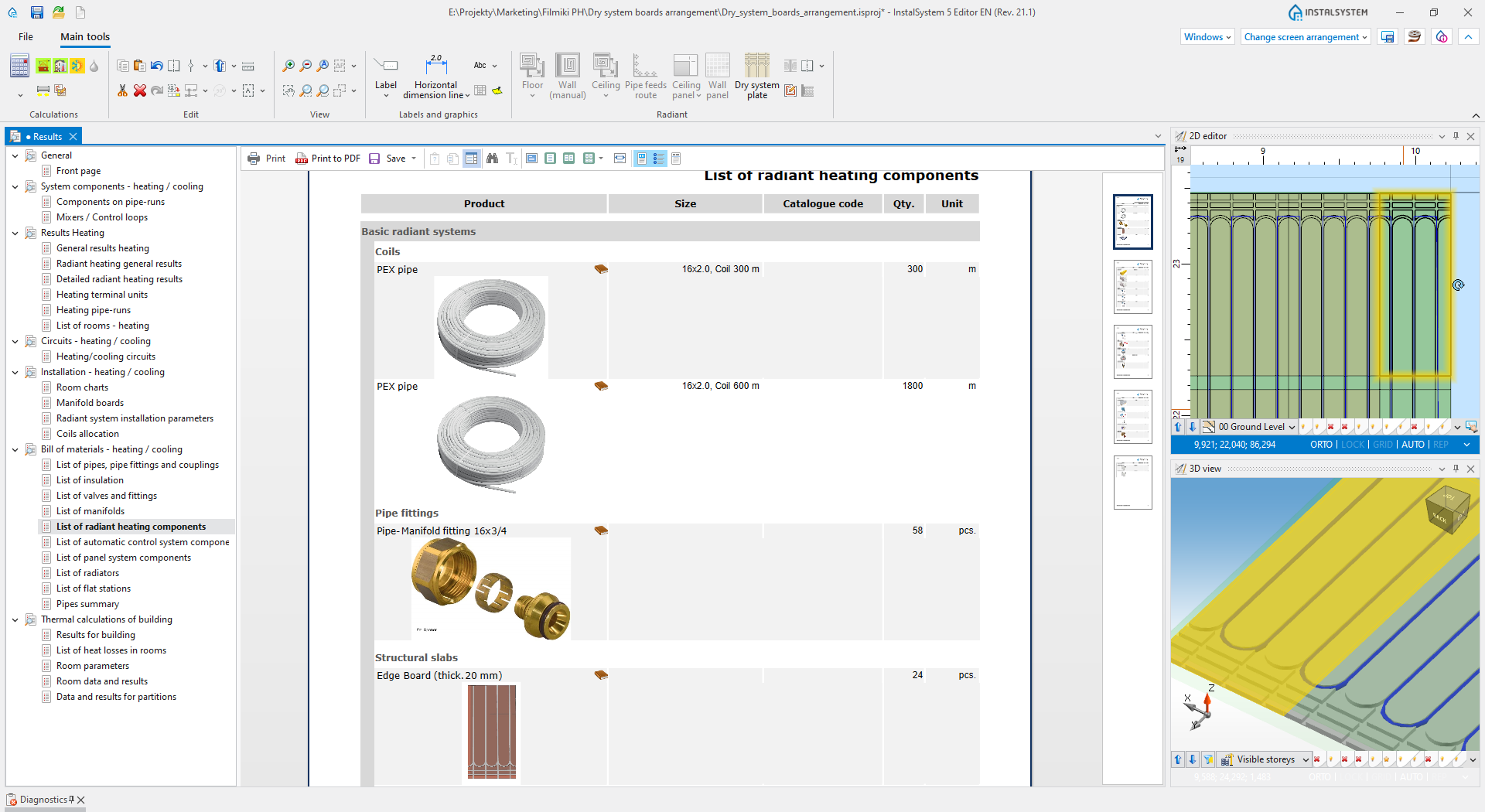
- Precise listing the number of system boards based on the plan view with the inserted dry system boards:
- Boards variants: main, transit etc. are defined in the ‘Catalogs of surface heating / cooling systems (basic)’
- The lamellas are integrated with the boards (not separately inserted)
- Automatic filling of the indicated area with boards, with automatic trimming the boards to the edge of the room
- Possibility of quick manual boards arrangement, supported by the operating modes (AUTO and ORTO)
- Possibility of further use of trimmed pieces of boards, which positively influences the optimization of bill of materials
- Visualization of boards in 3D and on printouts
- Automatic generation of loop drawings in an appropriate layout with the possibility of manual corrections supported by a drawing grid (GRID mode)
List of standards and methods used for sizing and calculations

The module provides the possibility of designing any heating system, including network and fitting sizing and hydronic balancing. Any kind of heating terminal (including fan-coils) is simulated by a ‘Receptor with known hydraulic resistance’. Together with the ‘Radiator sizing’ module, convective radiator systems can be designed. Together with the ‘Radiant systems’ module, the following radiant systems can be designed: floors (including those with return temperature limiter), walls, ceilings. In combination with the ‘Panel systems’ module, modular panel systems can be designed. In projects with a common heat source for both convective and radiant systems, it is possible to use mixers or pump-mixing sets to obtain temperatures appropriate for radiant systems.

The module provides the possibility of designing cooling system (it is equivalent to the ‘Heating systems’ module). It supports various types of convection receivers (fan-coils, passive refrigeration beams) simulated by a common ‘Receptor’ with imposed resistance. Together with the ‘Radiant systems’ module, the following radiant systems can be designed: floors, walls, ceilings. In combination with the ‘Radiant panels’ module, panel systems can be designed in cooling mode. In both cases, cooling calculations can be made regardless of the heating mode. In projects with a common source for convective and radiant systems, it is possible to use mixers or pump-mixing sets to obtain temperatures appropriate for radiant systems.
The module enables to design heating and/or cooling prefaricated (ceilng, wall) panels. It supports prefabricated panels with loops placed in the filling (plaster, graphite or other) and appended steel panels. Such elements may be installed on the partition structure, on a metal framing (e.g. in appended ceilings) or appended as separate units (in case of appended panels).
- The most important functionalities of the module:
- Automatic completion of a given zone with ceiling panels (taking into consideration the panel’s type, optional dimensions and additional geopmetric guidelines)
- Possibility to arrange ceiling and wall panels manually
- Possibility to join panels as sets in series
- Calculation o thermal (heating and/or cooling) output on the basis of catalogue data and working parameters of the system (i.e. deltaT, ti) according:
- Hydraulic calculations, including calculation of deltaT for the medium flowing in the panel or in a set of panels in series in order to obtain required thermal output and hydraulic resistance according to:
- Diagnostics for exceeding max. velocity of medium flow in the panel
- Diagnostics for exceeding admissible pressure loss (dpmax) in the panel
- Diagnostics of laminar flow and subsequent output loss
- Additional functionalities for Zehnder radiant panels:
- Automatic distribution of panels according to Zehnder’s know-how in order to obtain equal radiation for the heated room
- Diagnostics of min. required number of panel rows (if specified by the user) in order to obtain equal radiation for the heated room
The ‘Dry system board arrangement’ module extends the functionality offered by the ‘Radiant systems’ module (in terms of underfloor heating systems) with the possibility of using dry system boards in the project. The module offers the following additional functionality:
- Precise listing the number of system boards based on the plan view with the inserted dry system boards:
- Boards variants: main, transit etc. are defined in the ‘Catalogs of surface heating / cooling systems (basic)’
- The lamellas are integrated with the boards (not separately inserted)
- Automatic filling of the indicated area with boards, with automatic trimming the boards to the edge of the room
- Possibility of quick manual boards arrangement, supported by the operating modes (AUTO and ORTO)
- Possibility of further use of trimmed pieces of boards, which positively influences the optimization of bill of materials
- Visualization of boards in 3D and on printouts
- Automatic generation of loop drawings in an appropriate layout with the possibility of manual corrections supported by a drawing grid (GRID mode)
List of standards and methods used for sizing and calculations
The module provides the possibility of designing any heating system, including network and fitting sizing and hydronic balancing. Any kind of heating terminal (including fan-coils) is simulated by a ‘Receptor with known hydraulic resistance’. Together with the ‘Radiator sizing’ module, convective radiator systems can be designed. Together with the ‘Radiant systems’ module, the following radiant systems can be designed: floors (including those with return temperature limiter), walls, ceilings. In combination with the ‘Panel systems’ module, modular panel systems can be designed. In projects with a common heat source for both convective and radiant systems, it is possible to use mixers or pump-mixing sets to obtain temperatures appropriate for radiant systems.
The module provides the possibility of designing cooling system (it is equivalent to the ‘Heating systems’ module). It supports various types of convection receivers (fan-coils, passive refrigeration beams) simulated by a common ‘Receptor’ with imposed resistance. Together with the ‘Radiant systems’ module, the following radiant systems can be designed: floors, walls, ceilings. In combination with the ‘Radiant panels’ module, panel systems can be designed in cooling mode. In both cases, cooling calculations can be made regardless of the heating mode. In projects with a common source for convective and radiant systems, it is possible to use mixers or pump-mixing sets to obtain temperatures appropriate for radiant systems.

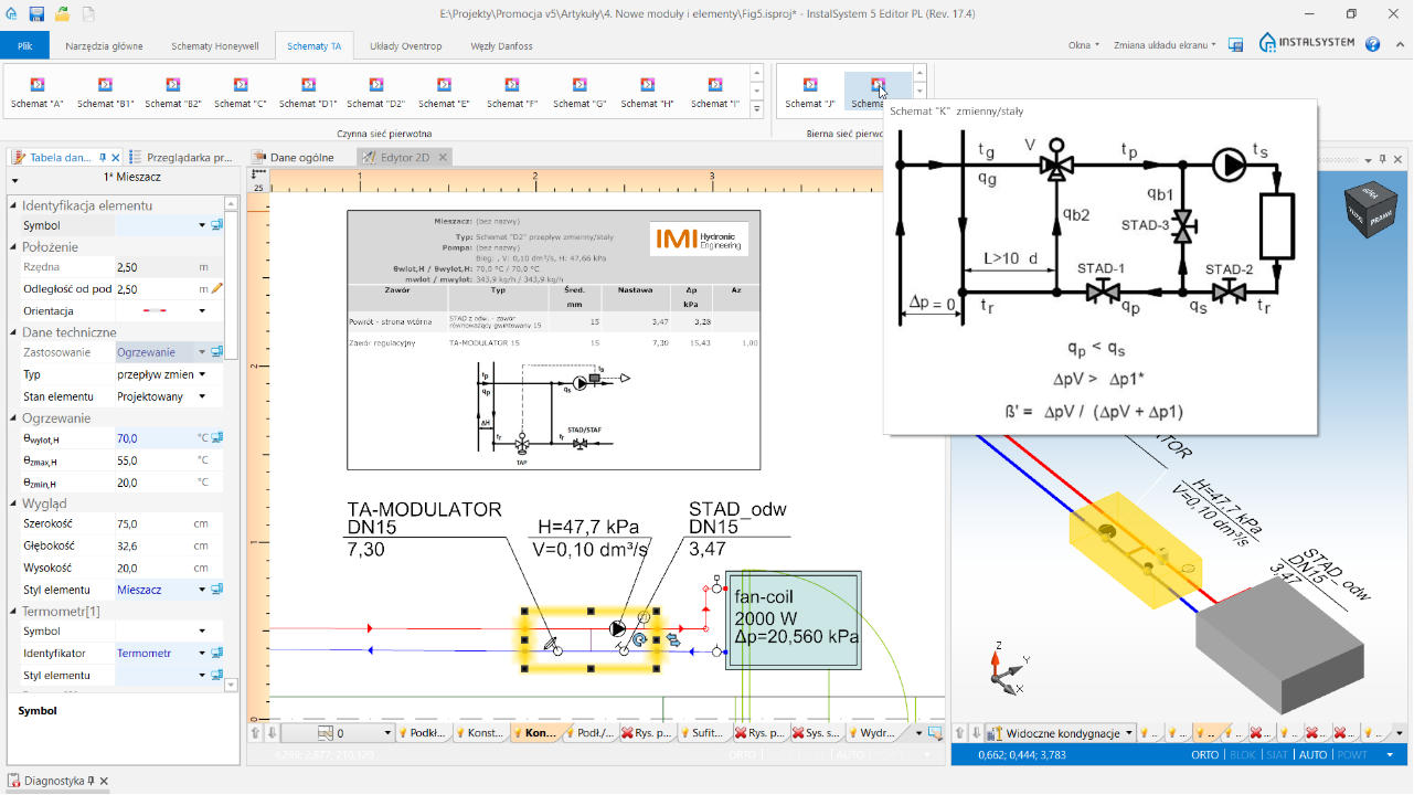
Hydraulic control loops are pre-defined set of elements (blocks with 2 entry points and 2 exit points, pump, balancing valves, etc.) saved in manufacturers catalogue, implemented in a manner consistent with the requirements of the manufacturer of this system in scope of:
- Balancing and regulating the installation
- Sizing of valve diameters
- Determination of valve settings
- Determination of pump working parameters
- Observing and diagnostics of other guidelines (e.g. required valve authority or preferred settings)
Hydraulic control loops are a unique configuration distinguishing feature of the program because they are prepared to meet specific customer requirements and their functionality is impossible to implement with elements and functions available as standard in the program. The use of hydraulic control loops in the project is simple and limited to inserting the finished block, from a dedicated additional toolbar tab, into the selected installation location. Configuration of hydraulic control loops allows their wide application in heating and cooling installations (receptors of various types and surface systems) eliminating, at the same time, potential and difficult to diagnose design errors (e.g. by limiting the availability of valves that cannot be used in specific installation solutions).
In InstalSystem 5, the possibility of using hydraulic control loops depends on the availability of a separate module package configuration called ‘Hydraulic control loops’ and the required catalogues.

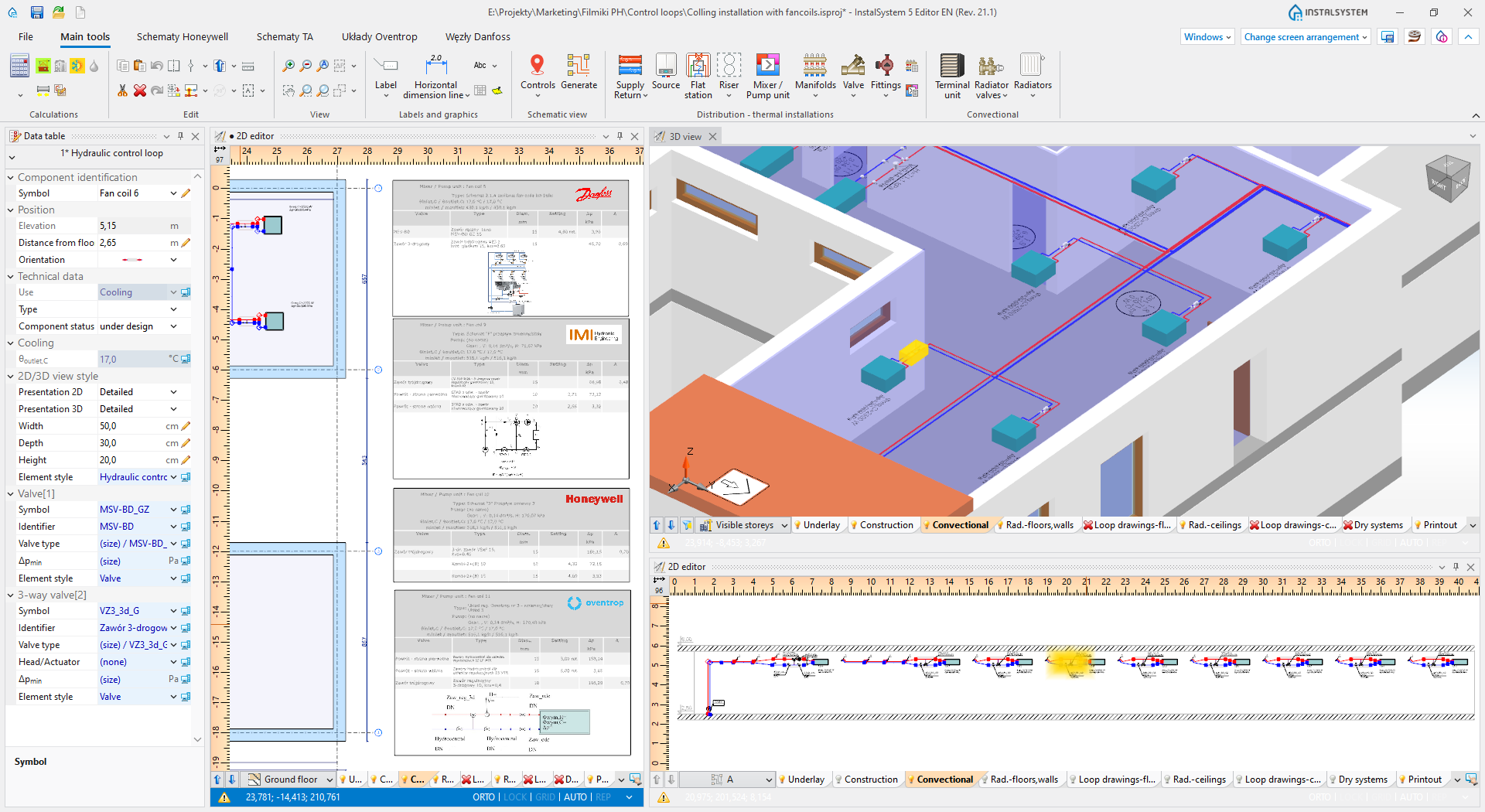
Watch also fragment of the tutorial about designing cooling systems, in which examples of hydraulic control loops are presented:

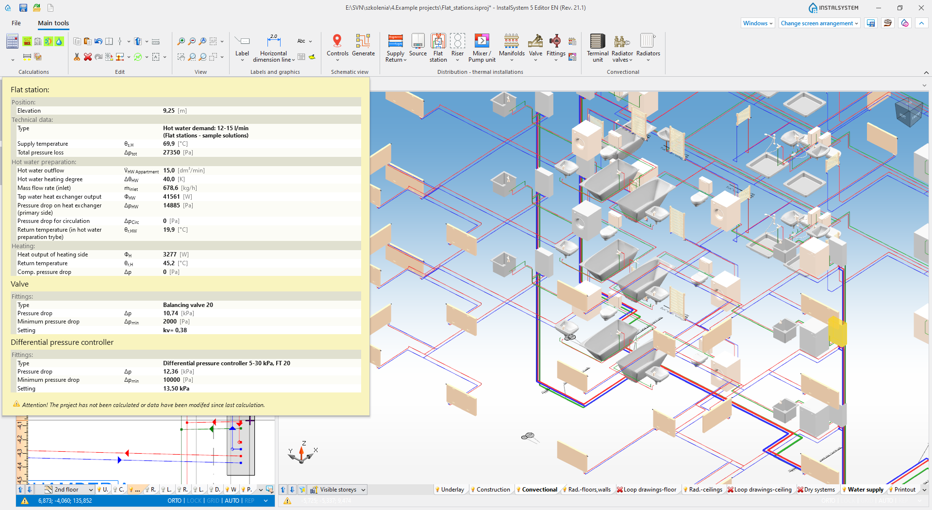
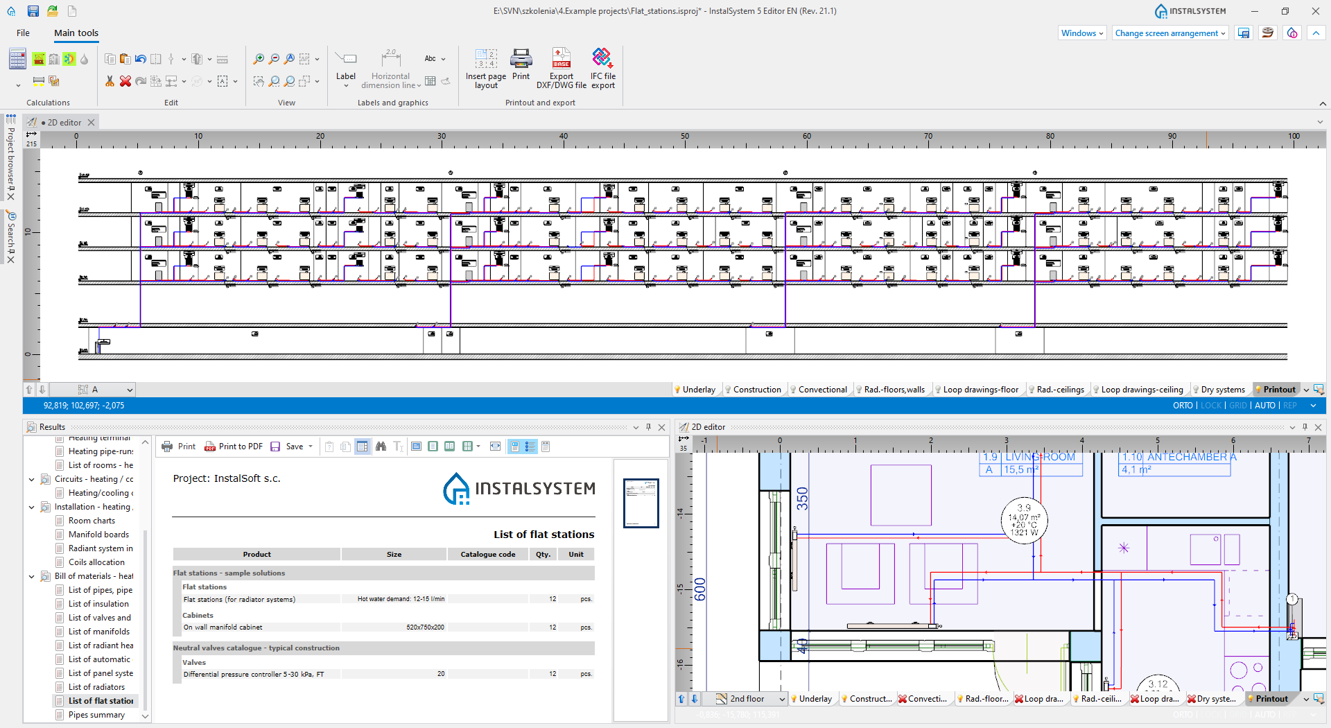
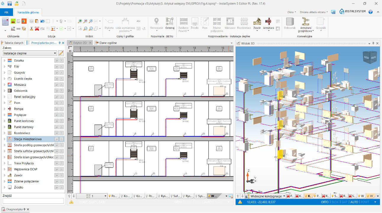
The module allows to use flat stations within the building’s technical infrastructure. Flat stations are represented in the program by a single-unit system element with precisely defined system connection points and with the possibility to customize its sub-elements and accessories.
- Use of flat stations in designs:
- Preparation (heating) of domestic hot water by an installed plate heat exchanger
- Distribution of the medium in the flat heating (convective and radiant) system
- Chosen essential functionalities realised by the module:
- Sizing of the installation feeding the stations
- Diagnostics of the necessary domestic hot water exchanger to obtain required outflow and heating of the domestic water with defined temperature of feeding the station with heating medium (exchanger dimensions are chosen manually by the user)
- Calculation of required supply system output which feeds the flat system installation
- Additional functions available for the Kamo stations:
- Calculations and presentation of the required buffer recipient capacity in the installation feeding flat stations according to the original KAMO methodology

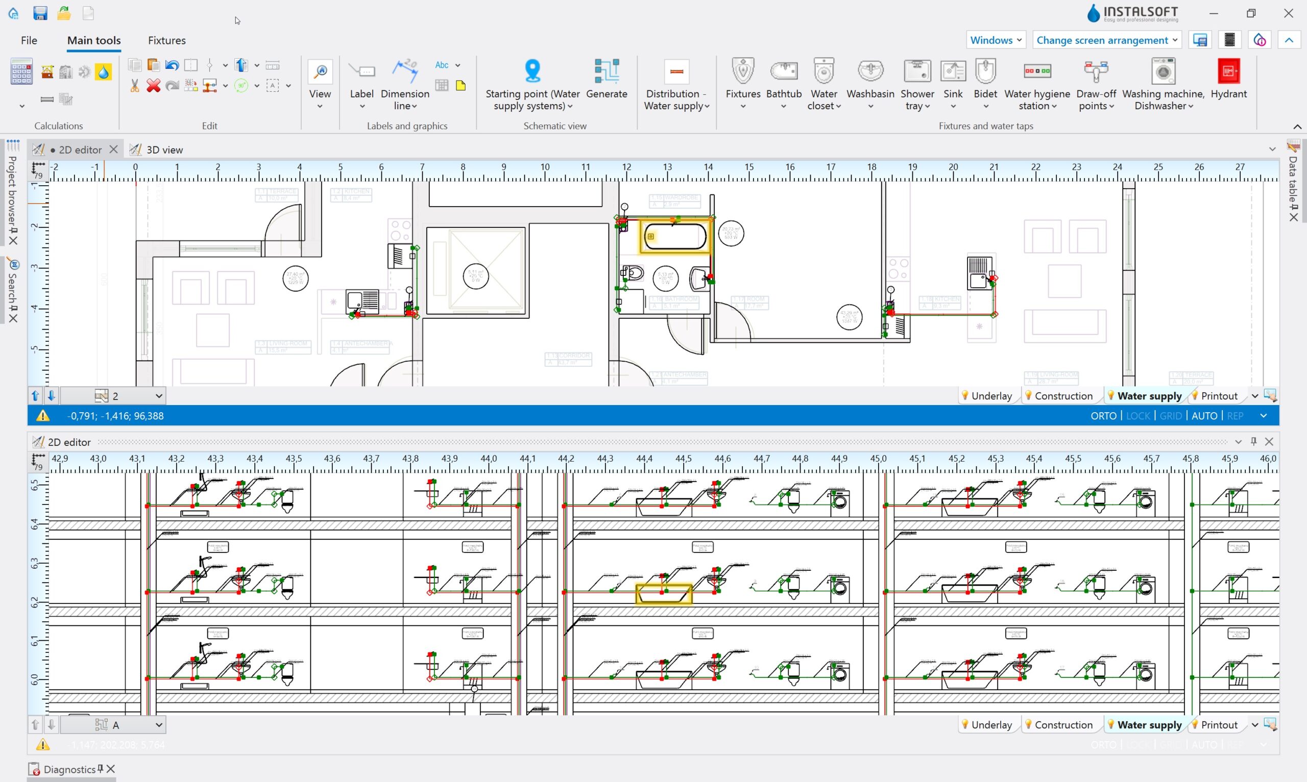
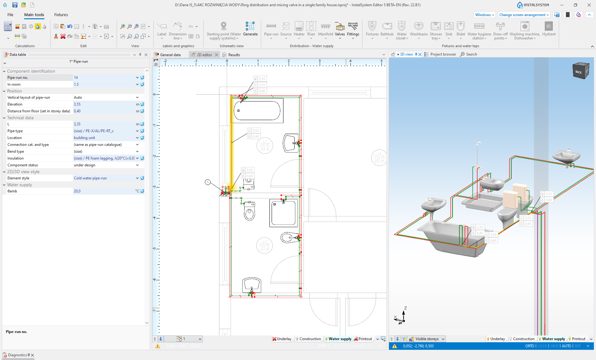
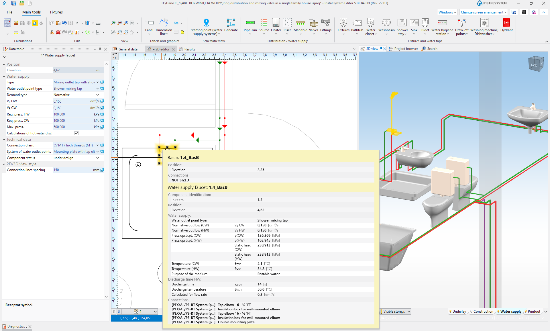
The module provides the ability to design water supply systems (hot and cold water, hot water circulation network). Includes graphical editing in the project, pipes and fittings sizing, 2D and 3D drawing presentation, hydraulic calculations, bill of materials. Sanitary accessories can be associated with water draw-off points, which results in a complete installation model together with sanitary equipment of the rooms.
When creating a project, a 3D model is created, which preview can be used to check compliance with the expected state. Model visualization may include installations designed (or designed) in other modules of the InstalSystem 5 package.
Hot and cold water residential installations can form rings (configuration extension required with the ‘Tap water extensions’ module). It is possible to use “Flat station” elements as water heaters (configuration extension with the ‘Flat stations’ module required).

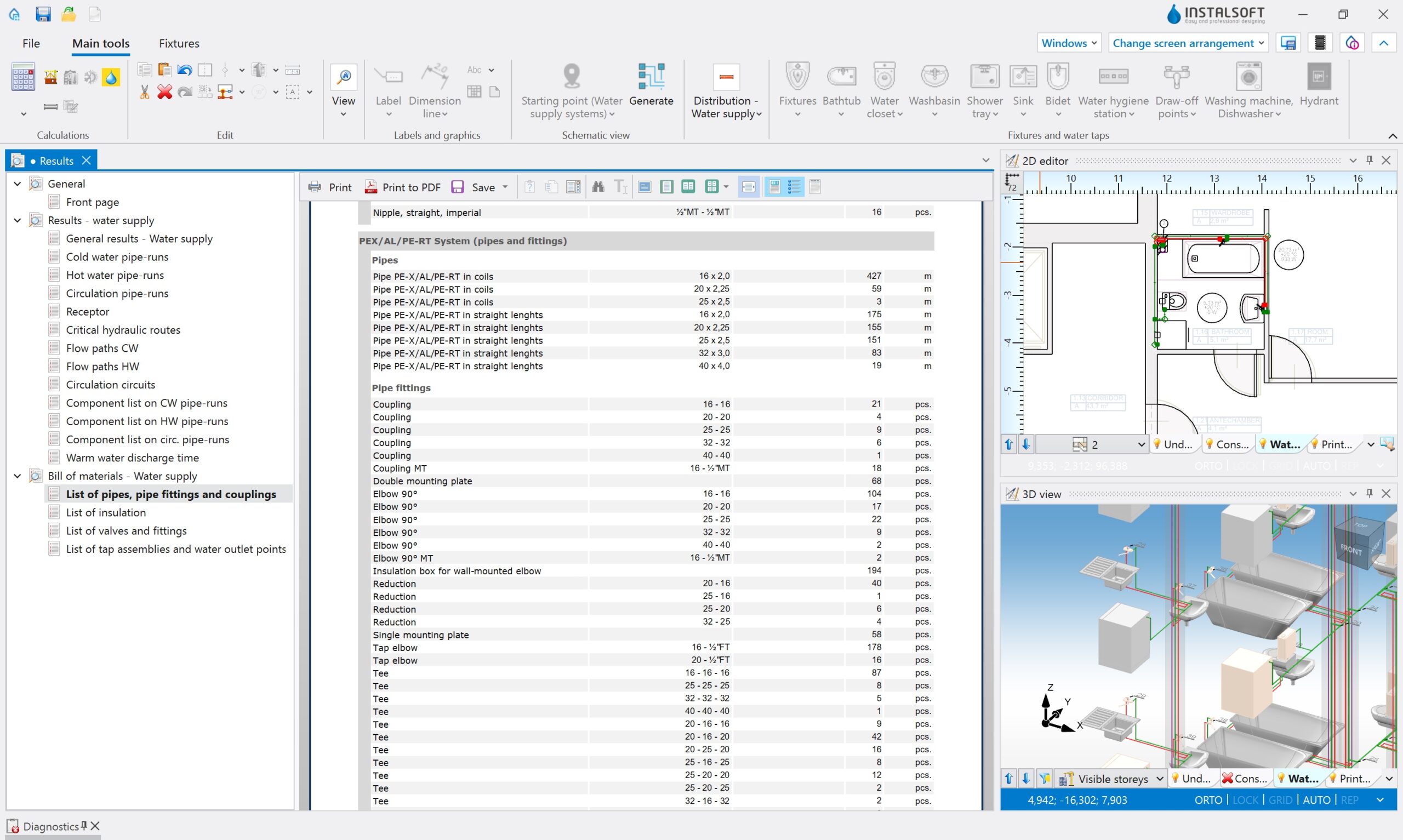

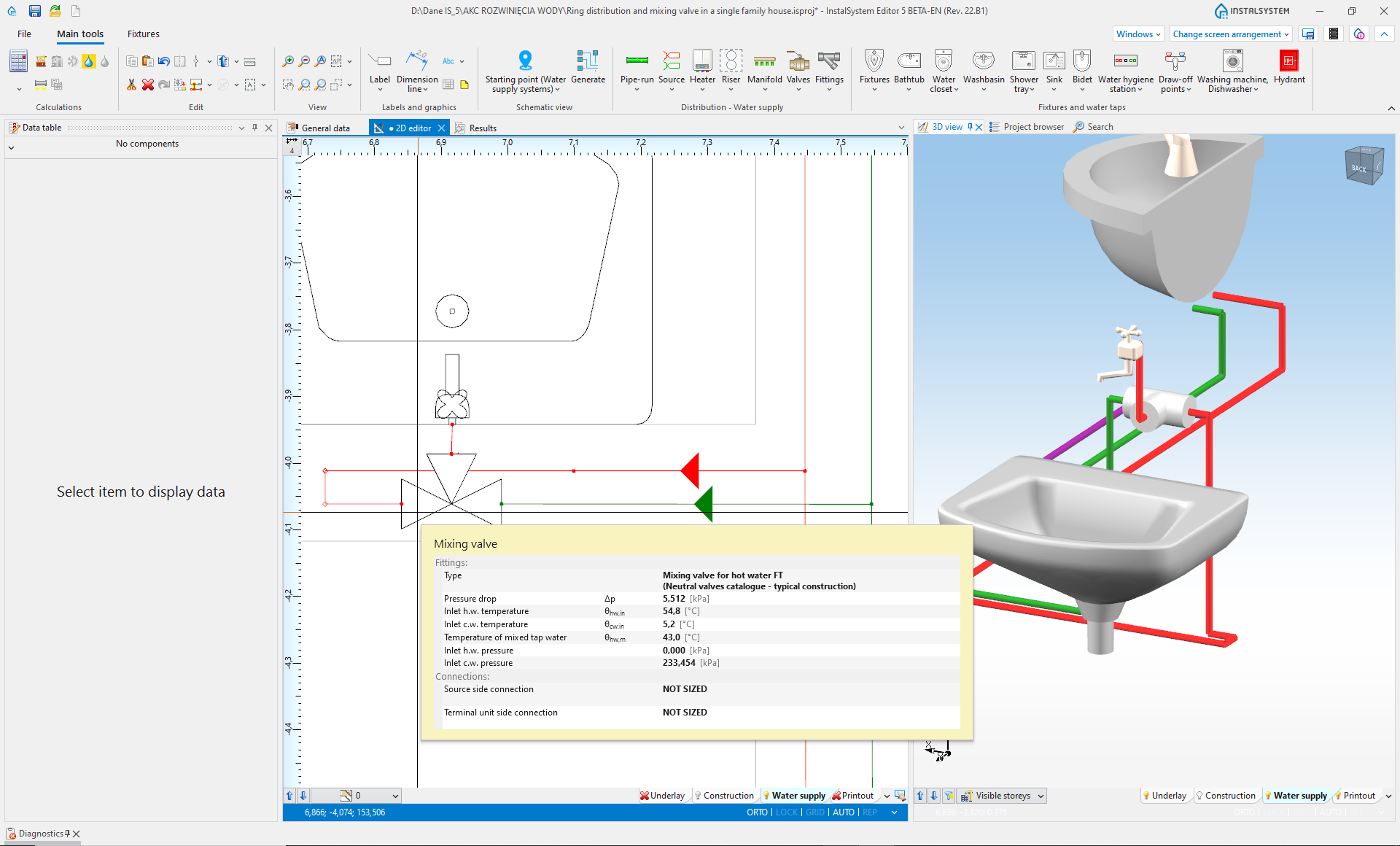
Extension to the ‘Water supply installations’. It provides additional advanced features in water supply design that go beyond the basic needs of some markets. Currently they are:
- Calculation of installations with temperature-reducing mixing valves, used in hospitals, common showers, etc.
- Calculation of hot water output time to draw-off points indicated in the project (requires usage of DIN 1988-300 designing standard)
- Calculation of rings covering single rings typically for residential installations
Hydraulic control loops are pre-defined set of elements (blocks with 2 entry points and 2 exit points, pump, balancing valves, etc.) saved in manufacturers catalogue, implemented in a manner consistent with the requirements of the manufacturer of this system in scope of:
- Balancing and regulating the installation
- Sizing of valve diameters
- Determination of valve settings
- Determination of pump working parameters
- Observing and diagnostics of other guidelines (e.g. required valve authority or preferred settings)
Hydraulic control loops are a unique configuration distinguishing feature of the program because they are prepared to meet specific customer requirements and their functionality is impossible to implement with elements and functions available as standard in the program. The use of hydraulic control loops in the project is simple and limited to inserting the finished block, from a dedicated additional toolbar tab, into the selected installation location. Configuration of hydraulic control loops allows their wide application in heating and cooling installations (receptors of various types and surface systems) eliminating, at the same time, potential and difficult to diagnose design errors (e.g. by limiting the availability of valves that cannot be used in specific installation solutions).
In InstalSystem 5, the possibility of using hydraulic control loops depends on the availability of a separate module package configuration called ‘Hydraulic control loops’ and the required catalogues.
Watch also fragment of the tutorial about designing cooling systems, in which examples of hydraulic control loops are presented:
The module allows to use flat stations within the building’s technical infrastructure. Flat stations are represented in the program by a single-unit system element with precisely defined system connection points and with the possibility to customize its sub-elements and accessories.
- Use of flat stations in designs:
- Preparation (heating) of domestic hot water by an installed plate heat exchanger
- Distribution of the medium in the flat heating (convective and radiant) system
- Chosen essential functionalities realised by the module:
- Sizing of the installation feeding the stations
- Diagnostics of the necessary domestic hot water exchanger to obtain required outflow and heating of the domestic water with defined temperature of feeding the station with heating medium (exchanger dimensions are chosen manually by the user)
- Calculation of required supply system output which feeds the flat system installation
- Additional functions available for the Kamo stations:
- Calculations and presentation of the required buffer recipient capacity in the installation feeding flat stations according to the original KAMO methodology
The module provides the ability to design water supply systems (hot and cold water, hot water circulation network). Includes graphical editing in the project, pipes and fittings sizing, 2D and 3D drawing presentation, hydraulic calculations, bill of materials. Sanitary accessories can be associated with water draw-off points, which results in a complete installation model together with sanitary equipment of the rooms.
When creating a project, a 3D model is created, which preview can be used to check compliance with the expected state. Model visualization may include installations designed (or designed) in other modules of the InstalSystem 5 package.
Hot and cold water residential installations can form rings (configuration extension required with the ‘Tap water extensions’ module). It is possible to use “Flat station” elements as water heaters (configuration extension with the ‘Flat stations’ module required).
Extension to the ‘Water supply installations’. It provides additional advanced features in water supply design that go beyond the basic needs of some markets. Currently they are:
- Calculation of installations with temperature-reducing mixing valves, used in hospitals, common showers, etc.
- Calculation of hot water output time to draw-off points indicated in the project (requires usage of DIN 1988-300 designing standard)
- Calculation of rings covering single rings typically for residential installations

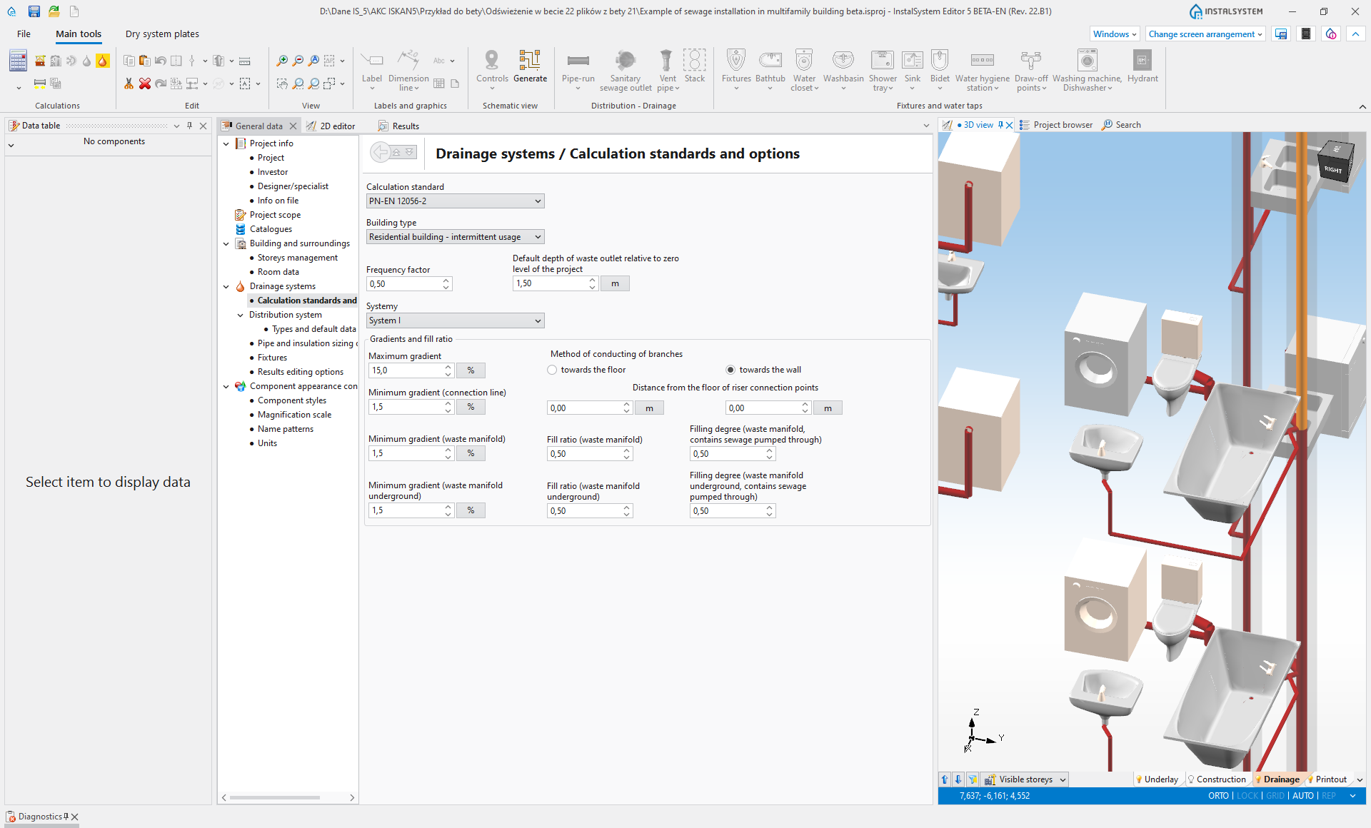
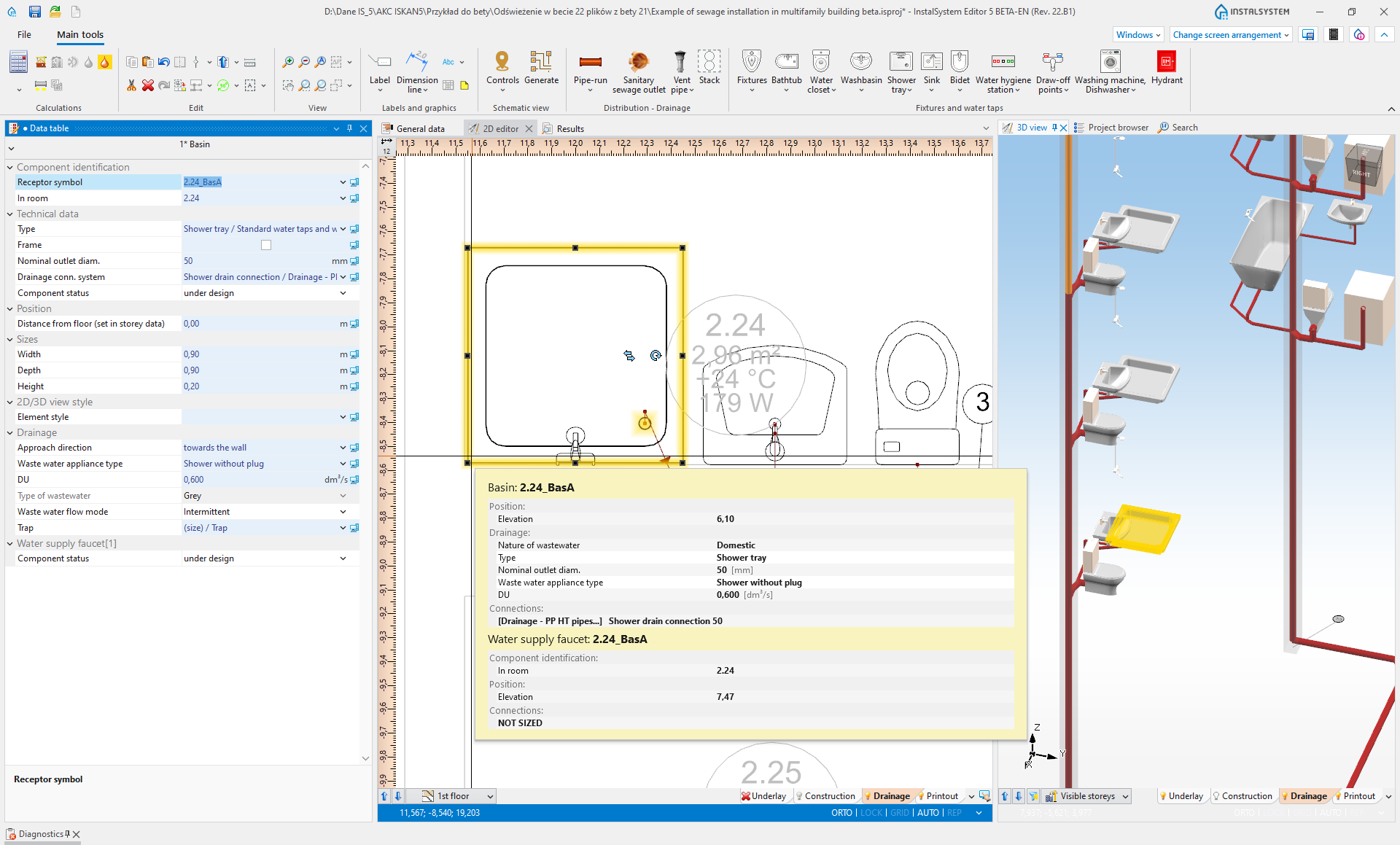
DOMESTIC WASTEWATER GRAVITY SYSTEMS
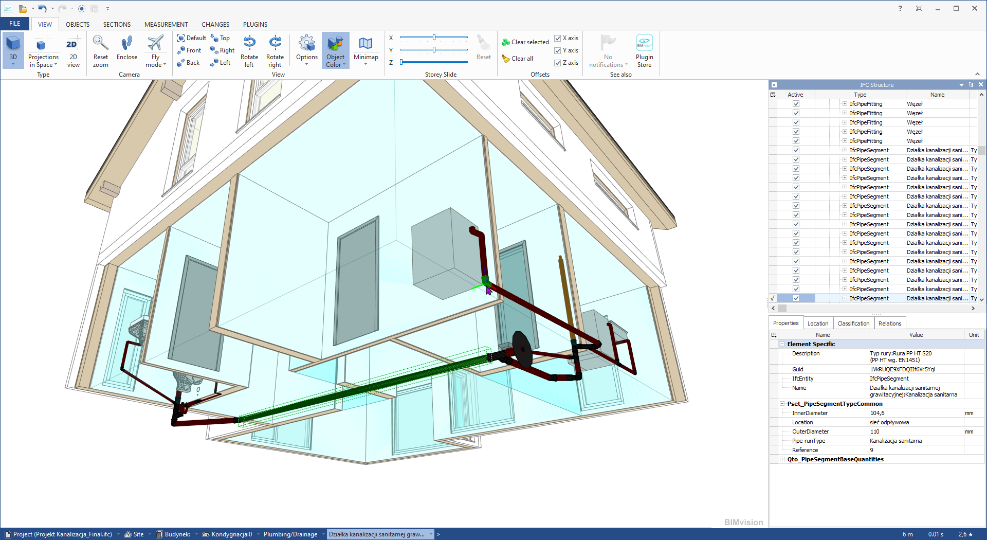
The module provides the possibility of designing internal gravity sewage systems. It includes graphic editing, selection of pipelines (pipe diameters, fittings), 2D and 3D drawing presentation, bill of materials. It takes into account the sanitary appliances placed in the rooms, resulting in a complete model of the installation including the sanitary ware in the rooms. When the project is created, a 3D model is built, the preview of which can be used to check compliance with the expected state on an ongoing basis. The model takes into account the designed gradients of pipe-runs and, after calculations, also the fittings selected (depending on the catalogues used, they can be made visible in the model).
Stacks can have ventilation sections automatically generated, taking into account various bypass ventilation variants. Before and after the calculation, an in-depth diagnostic of the installation geometry is carried out, considering the standard requirements with regard to route lengths, number of changes of direction, ventilation, etc.
Visualisation of the model can take into account installations designed in other modules of InstalSystem 5 package, in particular the ‘Water supply installations‘ module. The calculated model can be exported in various formats, including IFC, provided that the relevant module is available in the configuration. If fittings are visualised, the exported model takes them into account.

DOMESTIC WASTEWATER GRAVITY SYSTEMS
The module provides the possibility of designing internal gravity sewage systems. It includes graphic editing, selection of pipelines (pipe diameters, fittings), 2D and 3D drawing presentation, bill of materials. It takes into account the sanitary appliances placed in the rooms, resulting in a complete model of the installation including the sanitary ware in the rooms. When the project is created, a 3D model is built, the preview of which can be used to check compliance with the expected state on an ongoing basis. The model takes into account the designed gradients of pipe-runs and, after calculations, also the fittings selected (depending on the catalogues used, they can be made visible in the model).
Stacks can have ventilation sections automatically generated, taking into account various bypass ventilation variants. Before and after the calculation, an in-depth diagnostic of the installation geometry is carried out, considering the standard requirements with regard to route lengths, number of changes of direction, ventilation, etc.
Visualisation of the model can take into account installations designed in other modules of InstalSystem 5 package, in particular the ‘Water supply installations‘ module. The calculated model can be exported in various formats, including IFC, provided that the relevant module is available in the configuration. If fittings are visualised, the exported model takes them into account.

In InstalSystem 5 there is available, implemented prototype data import from the gbXML (Green Building XML) format, which is part of the BIM technology. Import includes elements of the building structure: floors, rooms, walls with windows, doors and other openings.

Modul ‘IFC (BIM) import bazowy’ omogućuje uvoz različitih objekata klase IFC4 i IFC2x3 (iz područja konstrukcije, instalacija i ostalo), bez njihove interpretacije. Moguće je učitavanje više modela istovremeno. Objekti su vidljivi kako za 2D uređivač tako i za 3D prikaz. Upravljanje uvezenim modelom omogućava poseban Preglednik projekta i informacije vidljive u Tablici podataka. Objekti iz modela mogu se označavati ili skrivati. Također su vidljivi za funkciju SNAP prilikom uređivanja drugih područja u 2D uređivaču. Modeli (kao cjelina) mogu biti brisani ili ponovno uvoženi.
Modeli učitani korištenjem ovog modula mogu se interpretirati u pogledu građevinske konstrukcije zajedno s ‘IFC (BIM) interpretacija podataka o zgradi’. Samo geometrija modela može služiti kao pozadina za instalacije koje se projektuju u InstalSystemu 5, bez potrebe za interpretacijom. Rad s modelom također omogućuje otkrivanje sudara objekata prisutnih u IFC-u s objektima instalacija projektiranih u InstalSystemu 5. Modeli IFC-a podložni su izvozu u DXF/DWG i PDF formate.
DOMESTIC WASTEWATER GRAVITY SYSTEMS
The module provides the possibility of designing internal gravity sewage systems. It includes graphic editing, selection of pipelines (pipe diameters, fittings), 2D and 3D drawing presentation, bill of materials. It takes into account the sanitary appliances placed in the rooms, resulting in a complete model of the installation including the sanitary ware in the rooms. When the project is created, a 3D model is built, the preview of which can be used to check compliance with the expected state on an ongoing basis. The model takes into account the designed gradients of pipe-runs and, after calculations, also the fittings selected (depending on the catalogues used, they can be made visible in the model).
Stacks can have ventilation sections automatically generated, taking into account various bypass ventilation variants. Before and after the calculation, an in-depth diagnostic of the installation geometry is carried out, considering the standard requirements with regard to route lengths, number of changes of direction, ventilation, etc.
Visualisation of the model can take into account installations designed in other modules of InstalSystem 5 package, in particular the ‘Water supply installations‘ module. The calculated model can be exported in various formats, including IFC, provided that the relevant module is available in the configuration. If fittings are visualised, the exported model takes them into account.
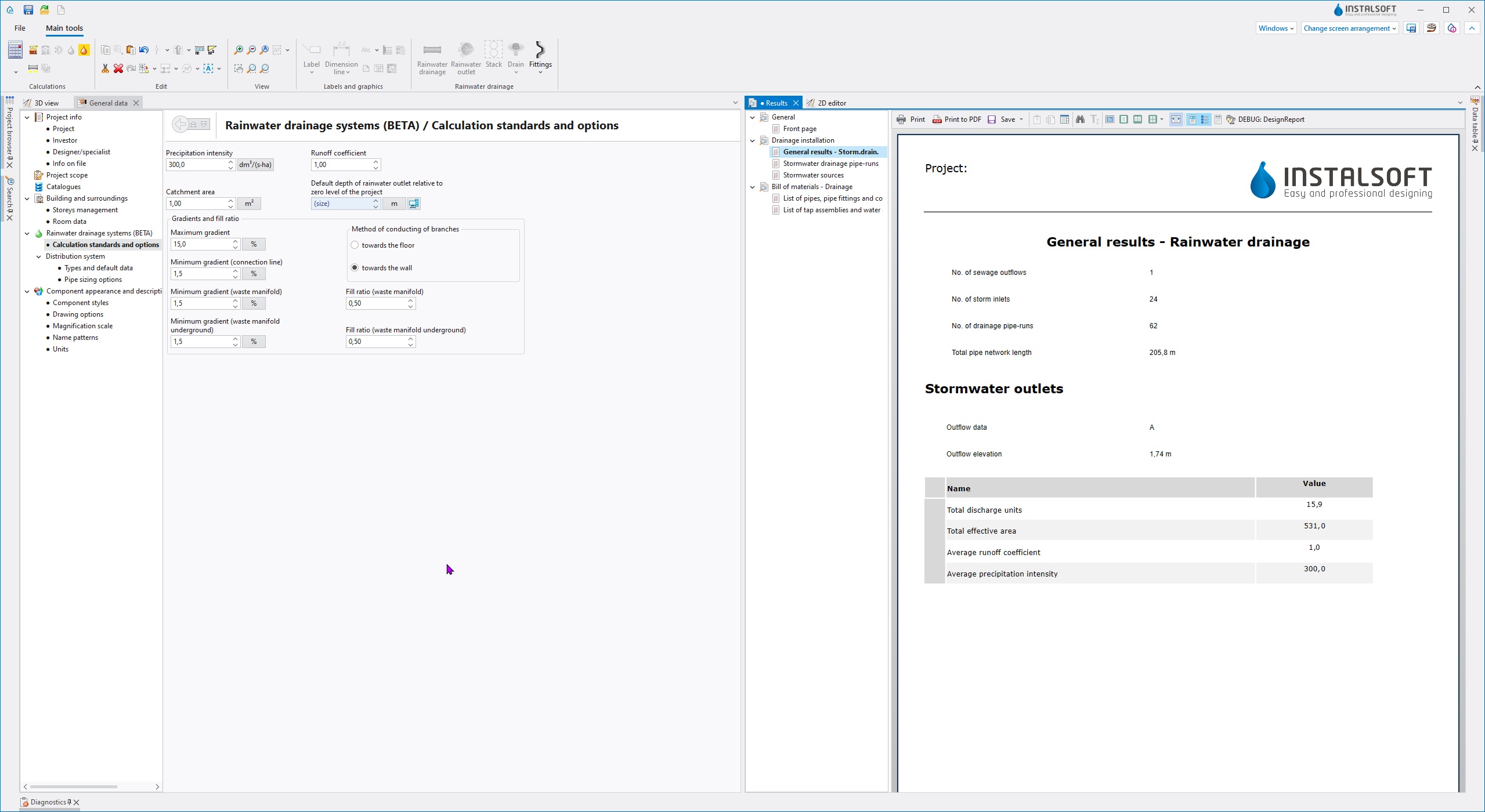
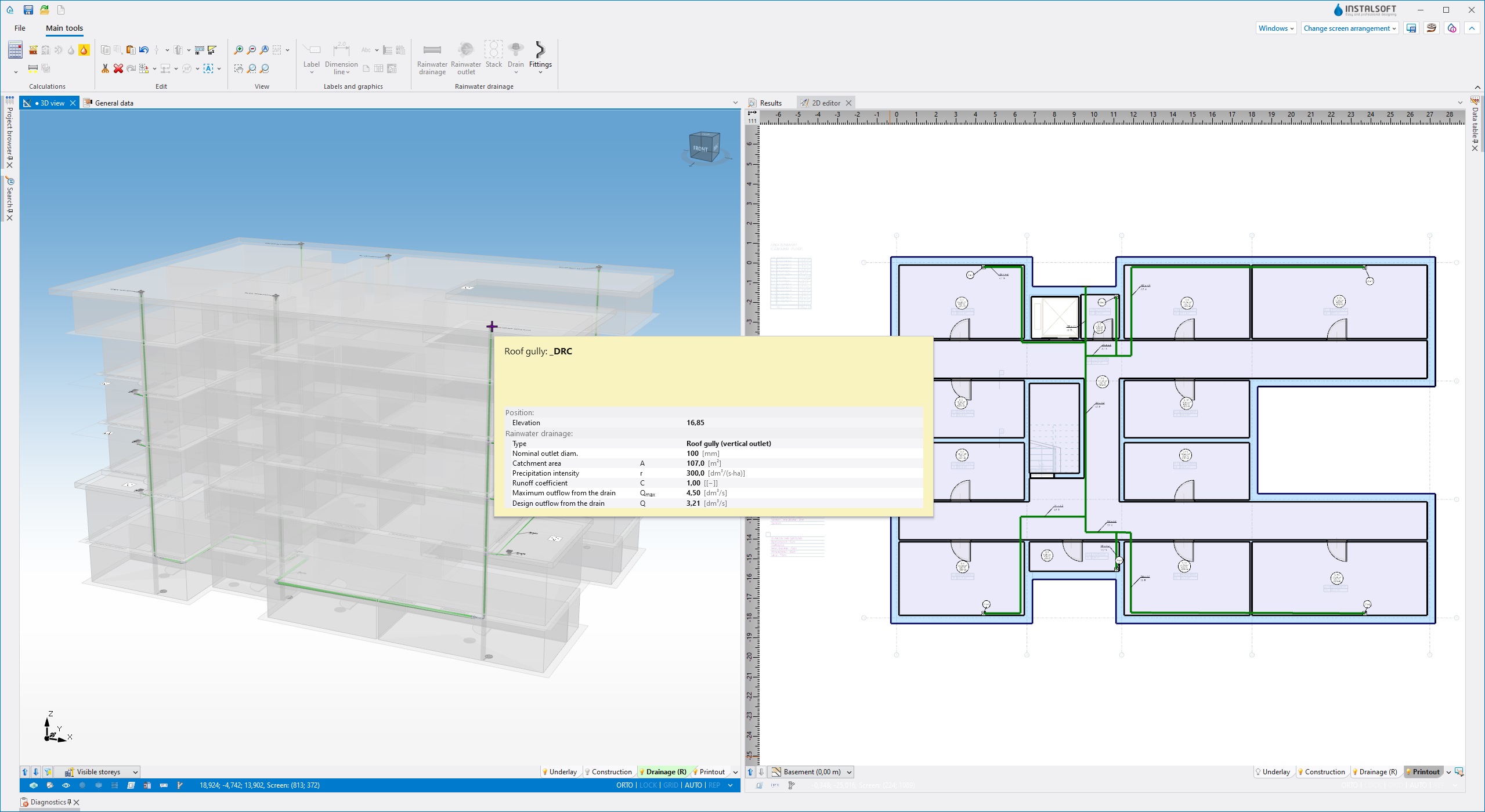
The module provides the possibility of designing rainwater drainage gravity systems for building roofs and their environment. It includes graphic editing, selection of pipelines (pipe diameters, fittings), 2D and 3D drawing presentation, bill of materials. In the course of project creation, a 3D model of the project is created, the preview of which can be used to control compliance with the expected state on an ongoing basis. Visualisation of the model can take into account installations designed (or in progress of designing) in other modules of InstalSystem 5 package.
(The publication of the complete version is planned for release 27.0)
In InstalSystem 5 there is available, implemented prototype data import from the gbXML (Green Building XML) format, which is part of the BIM technology. Import includes elements of the building structure: floors, rooms, walls with windows, doors and other openings.
Modul ‘IFC (BIM) import bazowy’ omogućuje uvoz različitih objekata klase IFC4 i IFC2x3 (iz područja konstrukcije, instalacija i ostalo), bez njihove interpretacije. Moguće je učitavanje više modela istovremeno. Objekti su vidljivi kako za 2D uređivač tako i za 3D prikaz. Upravljanje uvezenim modelom omogućava poseban Preglednik projekta i informacije vidljive u Tablici podataka. Objekti iz modela mogu se označavati ili skrivati. Također su vidljivi za funkciju SNAP prilikom uređivanja drugih područja u 2D uređivaču. Modeli (kao cjelina) mogu biti brisani ili ponovno uvoženi.
Modeli učitani korištenjem ovog modula mogu se interpretirati u pogledu građevinske konstrukcije zajedno s ‘IFC (BIM) interpretacija podataka o zgradi’. Samo geometrija modela može služiti kao pozadina za instalacije koje se projektuju u InstalSystemu 5, bez potrebe za interpretacijom. Rad s modelom također omogućuje otkrivanje sudara objekata prisutnih u IFC-u s objektima instalacija projektiranih u InstalSystemu 5. Modeli IFC-a podložni su izvozu u DXF/DWG i PDF formate.

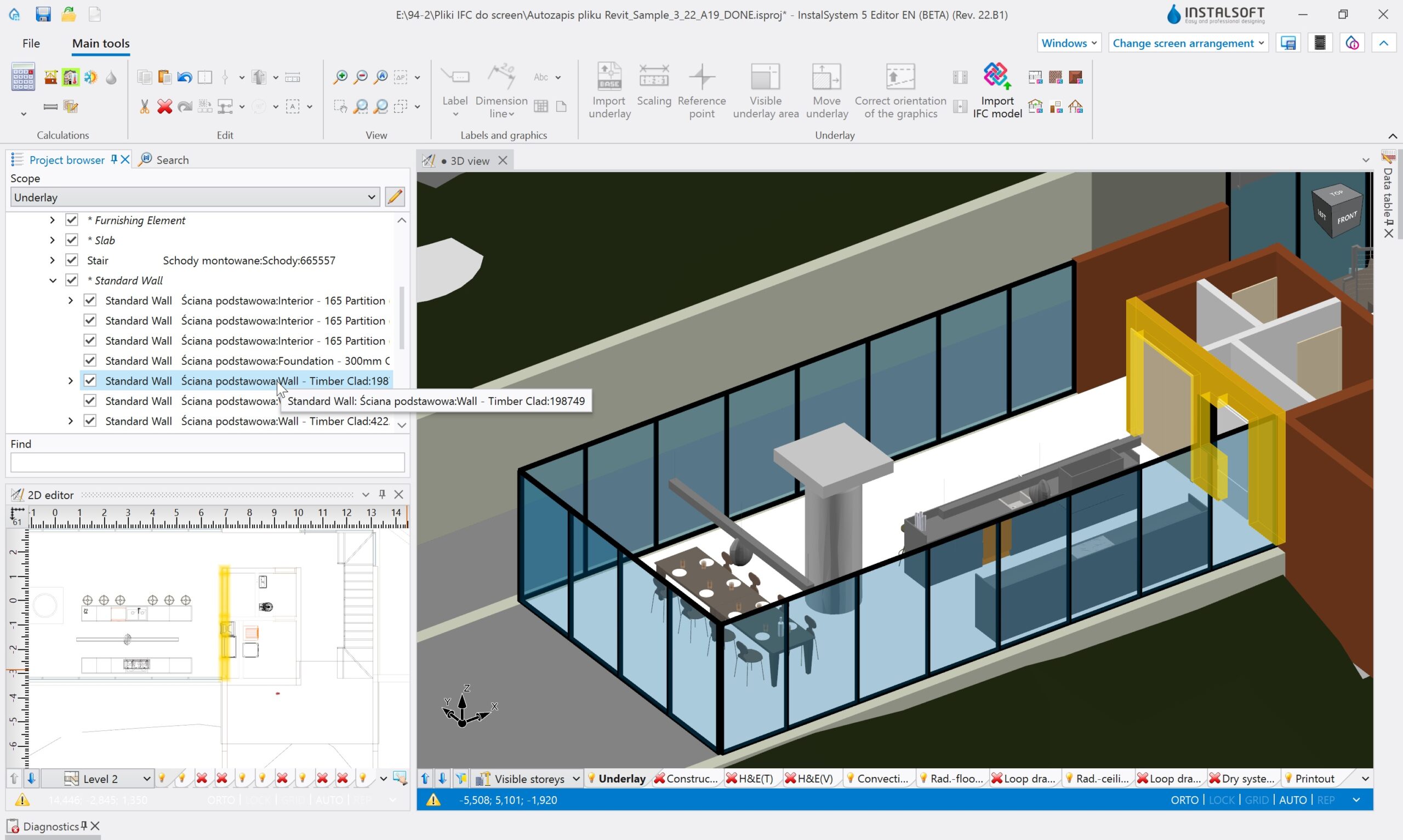
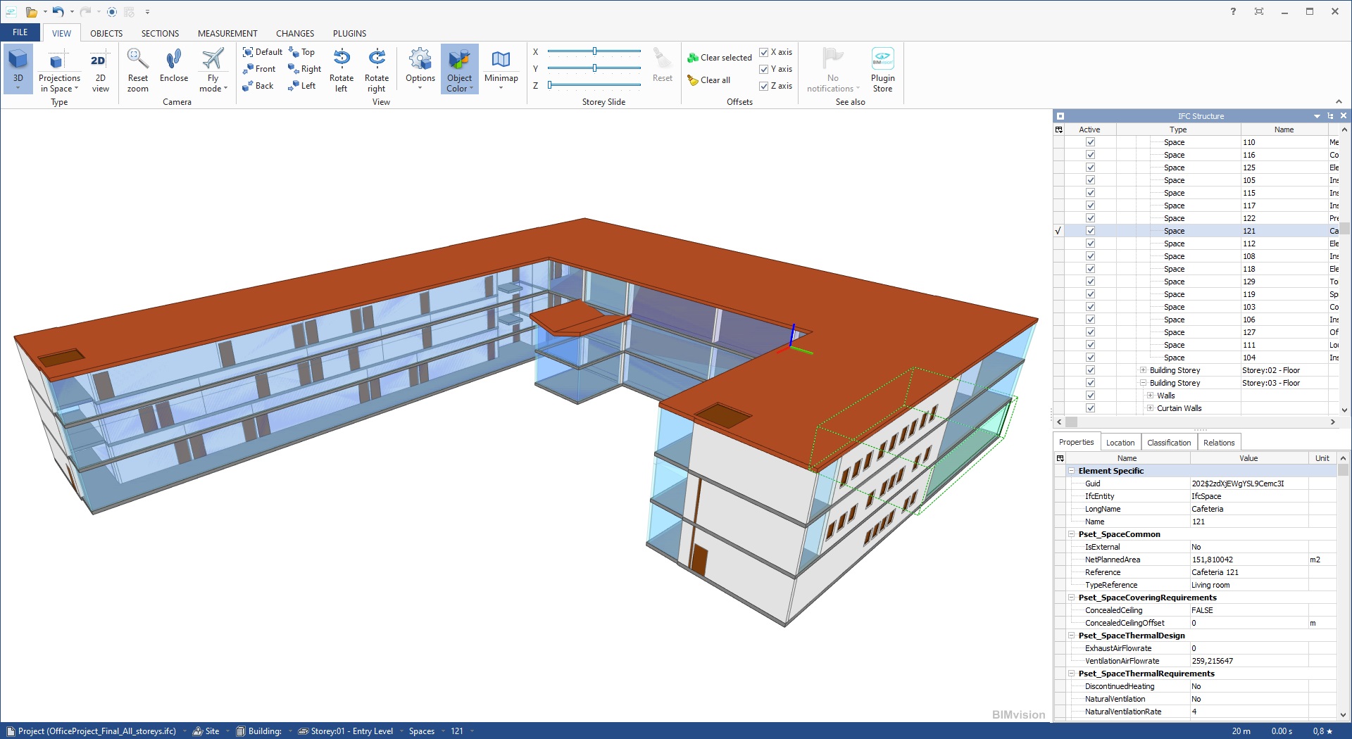
The ‘IFC (BIM) building data interpretation’ module enables highly automated interpretation of building structure objects imported from the IFC model. Interpretation covers such elements as: storeys (automatic or semi-automatic interpretation), walls with windows, doors and other openings, roofs, slabs with openings (automatic interpretation). A new feature is the automatic interpretation of rooms from ifcSpace objects.
The result of the interpretation is the appropriate native objects of the InstalSystem 5 software, forming a building structure ready for further editing and calculations. The resulting objects are independent of the loaded IFC model. This means that the building structure, obtained in such a highly automated manner, can be used for further design work in InstalSystem 5 – thermal calculations (heat load, energy performance) and as a basis for the design of heating, cooling and sanitary installations in the building.


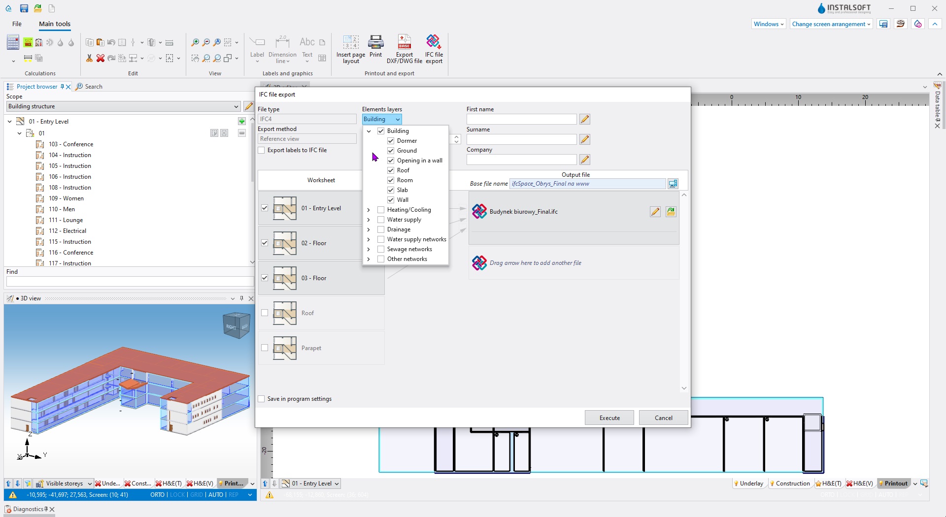
The ‘IFC (BIM) building structure elements export’ module enables the export of various IFC4 class objects in the field of building structure (horizontal/vertical partitions, sub-partitions and rooms along with their technical and calculation parameters).
The program exports construction projects designed in InstalSystem 5 to the IFC format, that entering the BIM path.
The building structure is exported based on the 3D model of the building and is part of the IFC Reference View export method defined by buildingSMART. The building export contains basic information about the name of objects and their properties, as well as an exact geometric representation of the objects.

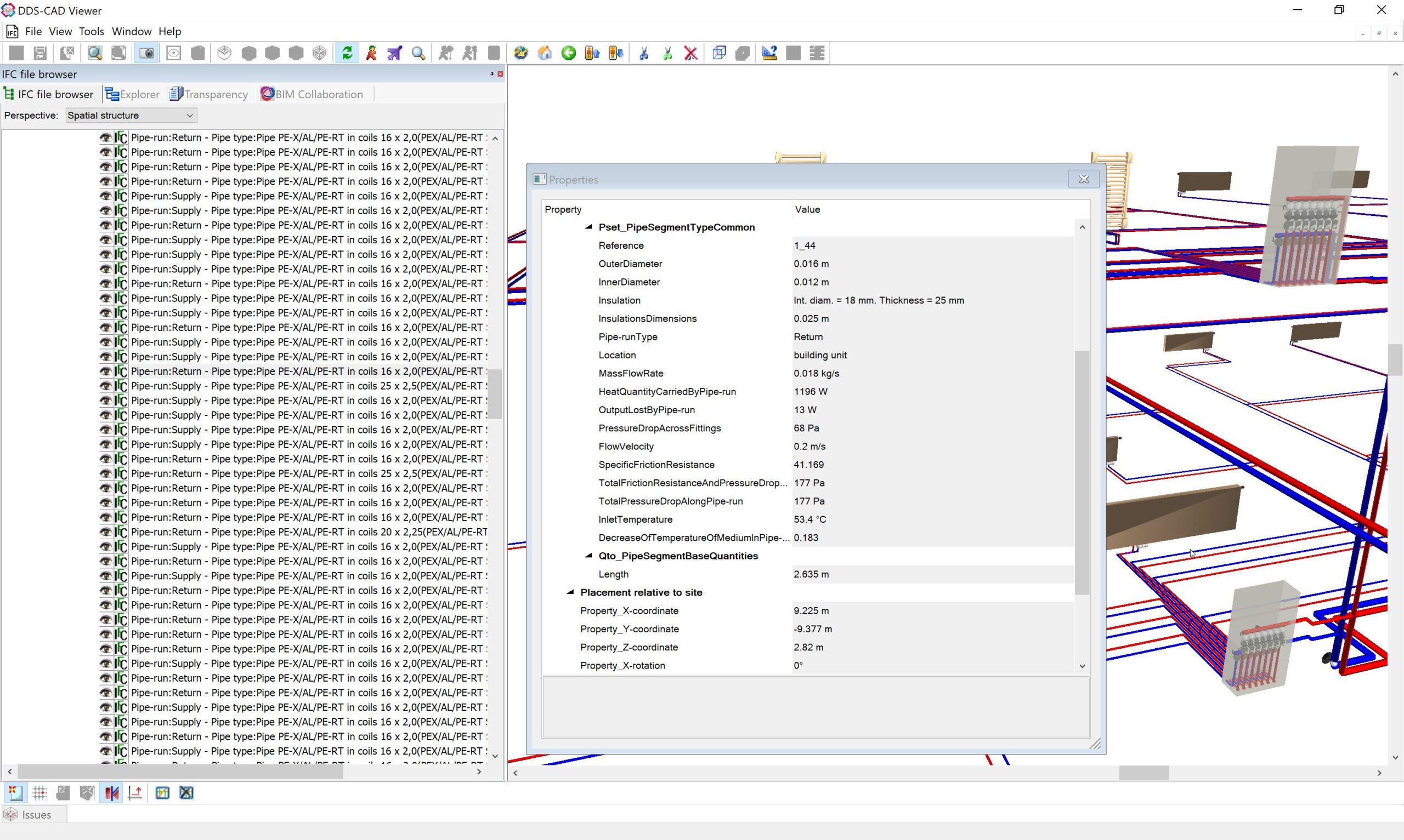
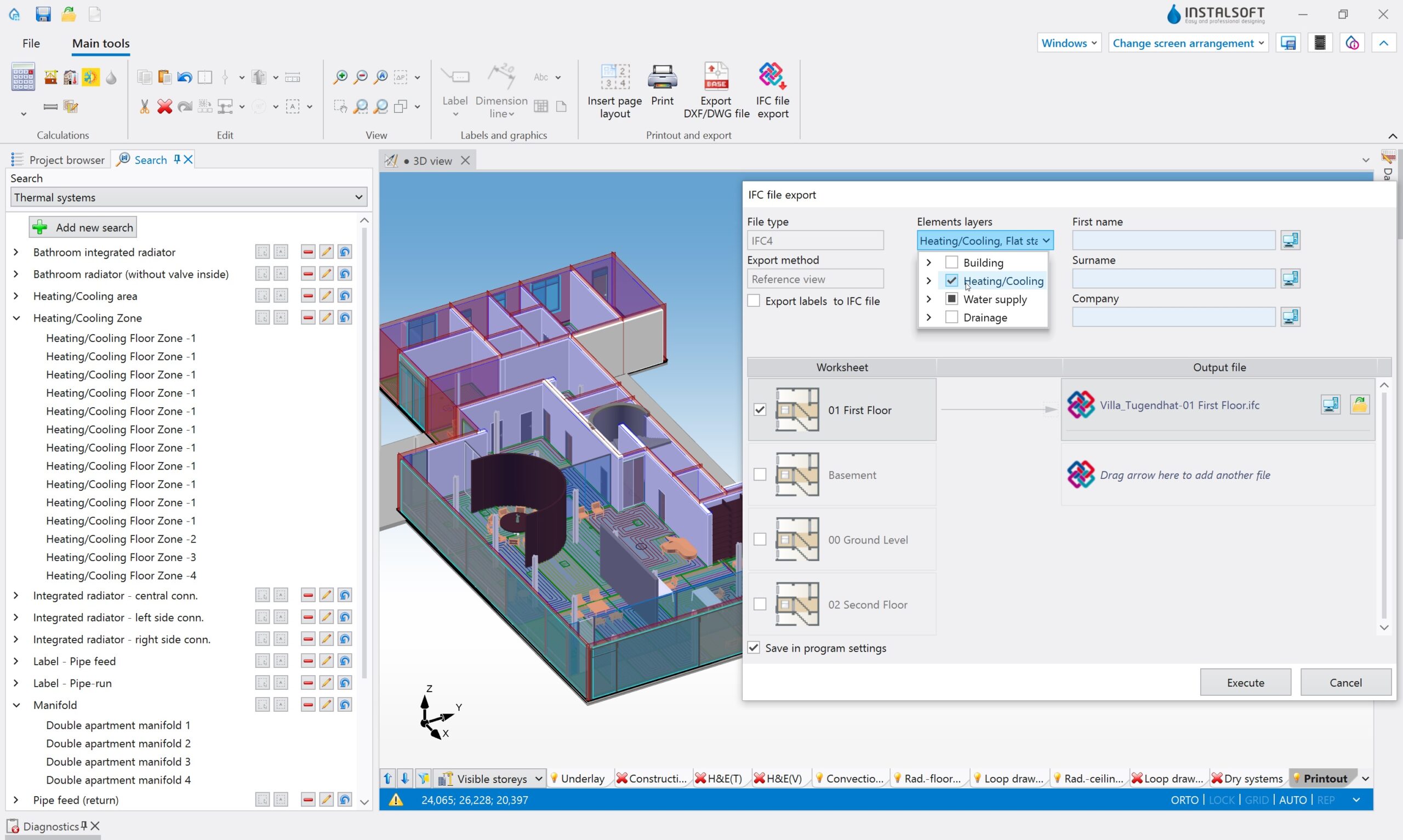
The ‘IFC (BIM) heating/cooling system export’ module enables the export of various IFC4 class objects in the field of heating/cooling installation.
The program exports installation projects designed in InstalSystem 5 to the IFC format, that entering the BIM path.
The installation is exported based on the 3D model of the installation and is part of the IFC Reference View export method defined by buildingSMART. The installation export contains basic information about the name of objects and their properties, as well as an exact geometric representation of the objects.
The elements such as Pipe-run, Pipe feed, Loop, Double apartment manifold and elements from the Valve category are currently subject to extended parameterization. All items with a catalog code are exported with this code.

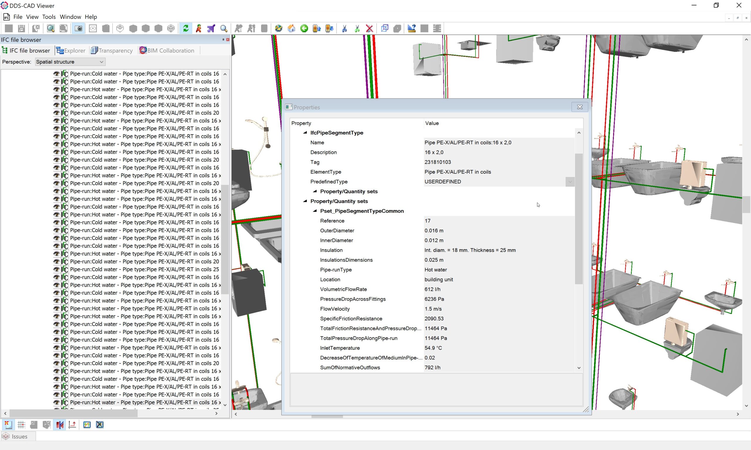
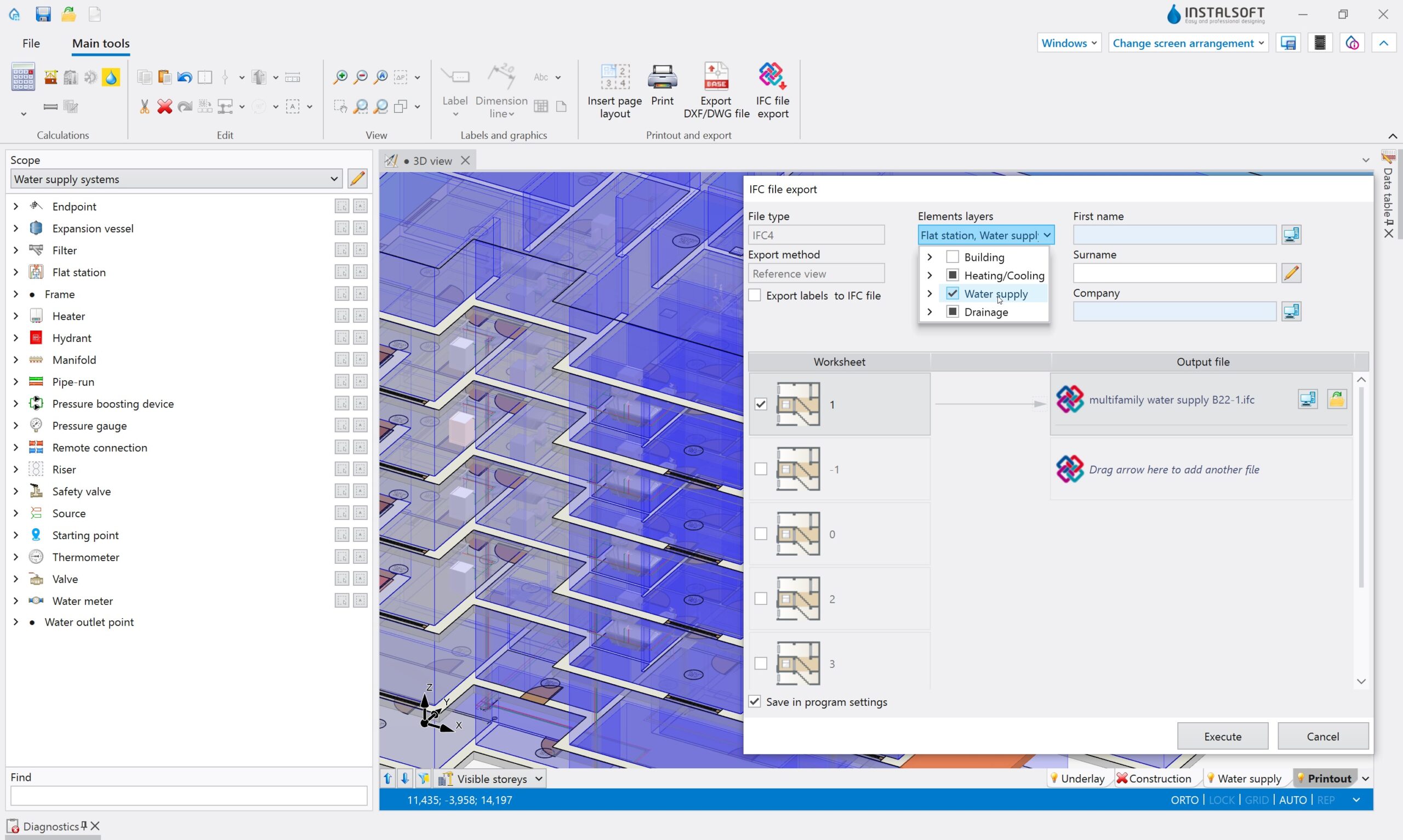
The ‘IFC (BIM) tap water system export’ module enables the export of various IFC4 class objects in the field of water supply installation.
The program exports installation projects designed in InstalSystem 5 to the IFC format, that entering the BIM path.
The installation is exported based on the 3D model of the installation and is part of the IFC Reference View export method defined by buildingSMART. The installation export contains basic information about the name of objects and their properties, as well as an exact geometric representation of the objects.
The elements such as Pipe-run and elements from the Valve category are currently subject to extended parameterization. All items with a catalog code are exported with this code.
The ‘IFC (BIM) building data interpretation’ module enables highly automated interpretation of building structure objects imported from the IFC model. Interpretation covers such elements as: storeys (automatic or semi-automatic interpretation), walls with windows, doors and other openings, roofs, slabs with openings (automatic interpretation). A new feature is the automatic interpretation of rooms from ifcSpace objects.
The result of the interpretation is the appropriate native objects of the InstalSystem 5 software, forming a building structure ready for further editing and calculations. The resulting objects are independent of the loaded IFC model. This means that the building structure, obtained in such a highly automated manner, can be used for further design work in InstalSystem 5 – thermal calculations (heat load, energy performance) and as a basis for the design of heating, cooling and sanitary installations in the building.
The ‘IFC (BIM) building structure elements export’ module enables the export of various IFC4 class objects in the field of building structure (horizontal/vertical partitions, sub-partitions and rooms along with their technical and calculation parameters).
The program exports construction projects designed in InstalSystem 5 to the IFC format, that entering the BIM path.
The building structure is exported based on the 3D model of the building and is part of the IFC Reference View export method defined by buildingSMART. The building export contains basic information about the name of objects and their properties, as well as an exact geometric representation of the objects.
The ‘IFC (BIM) heating/cooling system export’ module enables the export of various IFC4 class objects in the field of heating/cooling installation.
The program exports installation projects designed in InstalSystem 5 to the IFC format, that entering the BIM path.
The installation is exported based on the 3D model of the installation and is part of the IFC Reference View export method defined by buildingSMART. The installation export contains basic information about the name of objects and their properties, as well as an exact geometric representation of the objects.
The elements such as Pipe-run, Pipe feed, Loop, Double apartment manifold and elements from the Valve category are currently subject to extended parameterization. All items with a catalog code are exported with this code.
The ‘IFC (BIM) tap water system export’ module enables the export of various IFC4 class objects in the field of water supply installation.
The program exports installation projects designed in InstalSystem 5 to the IFC format, that entering the BIM path.
The installation is exported based on the 3D model of the installation and is part of the IFC Reference View export method defined by buildingSMART. The installation export contains basic information about the name of objects and their properties, as well as an exact geometric representation of the objects.
The elements such as Pipe-run and elements from the Valve category are currently subject to extended parameterization. All items with a catalog code are exported with this code.

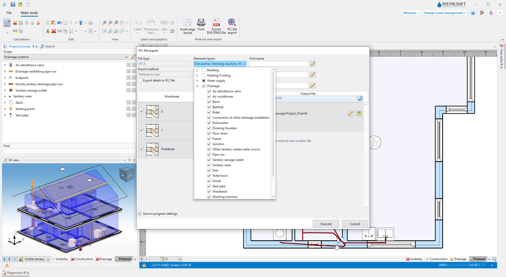
IFC SEWAGE SYSTEM EXPORT
The ‘IFC (BIM) sewage system export’ module enables the export of various IFC4 class objects in the field of domestic wastewater gravity systems.
The program exports installation projects designed in InstalSystem 5 to the IFC format, that entering the BIM path.
The installation is exported based on the 3D model of the installation and is part of the IFC Reference View export method defined by buildingSMART. The installation export contains basic information about the name of objects and their properties, as well as an exact geometric representation of the objects.
The elements such as Gravity sanitary drainage pipe-run (planned further development) and Drainage ventilating pipe run (planned further development) are currently subject to extended parameterization. All items with a catalog code are exported with this code. The export of the domestic wastewater gravity systems is performed with the Junction element.

The module allows to export a bill of materials, automatically generated by InstalSystem 5 calculation modules, to several available output formats:
- ISB file format, which is InstalSystem 4 project file, what allows it to be loaded into Instal-mat 4 for further processing
- to GAEB 81 and UGS formats, which are supported by some cost estimate programs
- to CSV format
It is possible to implement into the module other export formats or to integrate the module with the Partner’s order processing system. If you are interested in this option, please contact our sales department.

Interface for importing technical data of products contained in the files of the German VDI Open Standard (VDI 3805-6). The files themselves are not produced or distributed by InstalSoft – they are available on the websites of German software producers, producers of heaters and others.
The data contained in the files are processed to a limited extent (not all information is used by the program).

Interface for importing technical data of products contained in the files of the German open standard VDI (there are several versions of the specification of this standard). These files are not produced or distributed by InstalSoft – they are available on the websites of German software manufacturers, valve manufacturers and others.
The data contained in the files are processed to a limited extent (not all information is used by the program). In particular, not all valve types are supported – unsupported types are not “seen” by InstalSoft programs. Only valves for heating systems (VDI 3805 Blatt 2) are currently supported.
IFC SEWAGE SYSTEM EXPORT
The ‘IFC (BIM) sewage system export’ module enables the export of various IFC4 class objects in the field of domestic wastewater gravity systems.
The program exports installation projects designed in InstalSystem 5 to the IFC format, that entering the BIM path.
The installation is exported based on the 3D model of the installation and is part of the IFC Reference View export method defined by buildingSMART. The installation export contains basic information about the name of objects and their properties, as well as an exact geometric representation of the objects.
The elements such as Gravity sanitary drainage pipe-run (planned further development) and Drainage ventilating pipe run (planned further development) are currently subject to extended parameterization. All items with a catalog code are exported with this code. The export of the domestic wastewater gravity systems is performed with the Junction element.
The module allows to export a bill of materials, automatically generated by InstalSystem 5 calculation modules, to several available output formats:
- ISB file format, which is InstalSystem 4 project file, what allows it to be loaded into Instal-mat 4 for further processing
- to GAEB 81 and UGS formats, which are supported by some cost estimate programs
- to CSV format
It is possible to implement into the module other export formats or to integrate the module with the Partner’s order processing system. If you are interested in this option, please contact our sales department.
Interface for importing technical data of products contained in the files of the German VDI Open Standard (VDI 3805-6). The files themselves are not produced or distributed by InstalSoft – they are available on the websites of German software producers, producers of heaters and others.
The data contained in the files are processed to a limited extent (not all information is used by the program).
Interface for importing technical data of products contained in the files of the German open standard VDI (there are several versions of the specification of this standard). These files are not produced or distributed by InstalSoft – they are available on the websites of German software manufacturers, valve manufacturers and others.
The data contained in the files are processed to a limited extent (not all information is used by the program). In particular, not all valve types are supported – unsupported types are not “seen” by InstalSoft programs. Only valves for heating systems (VDI 3805 Blatt 2) are currently supported.
Available market versions


Discover the advantages of our software
InstalSystem 5 – the newest generation software for designing MEP & HVAC systems, is based on our 25 years of experience in collaboration with designers and leading manufacturers of MEP & HVAC systems and devices.
All the ideas and requests reported by InstalSystem 4 uses have allowed us to create an enhanced designing concept transformed into specific modules, functionalities, and tools. In this way, we have created a revolutionary tool, which defines a new quality in the engineering software market.
Enhanced ergonomics
The InstalSystem 5 package offers a variety of functionalities and tools improving working velocity and comfort. Some of them are simple, some of them are complex – their common goals are to elevate ergonomics to a higher level. Read about or chosen new tools and functionalities.
Integration of functional modules
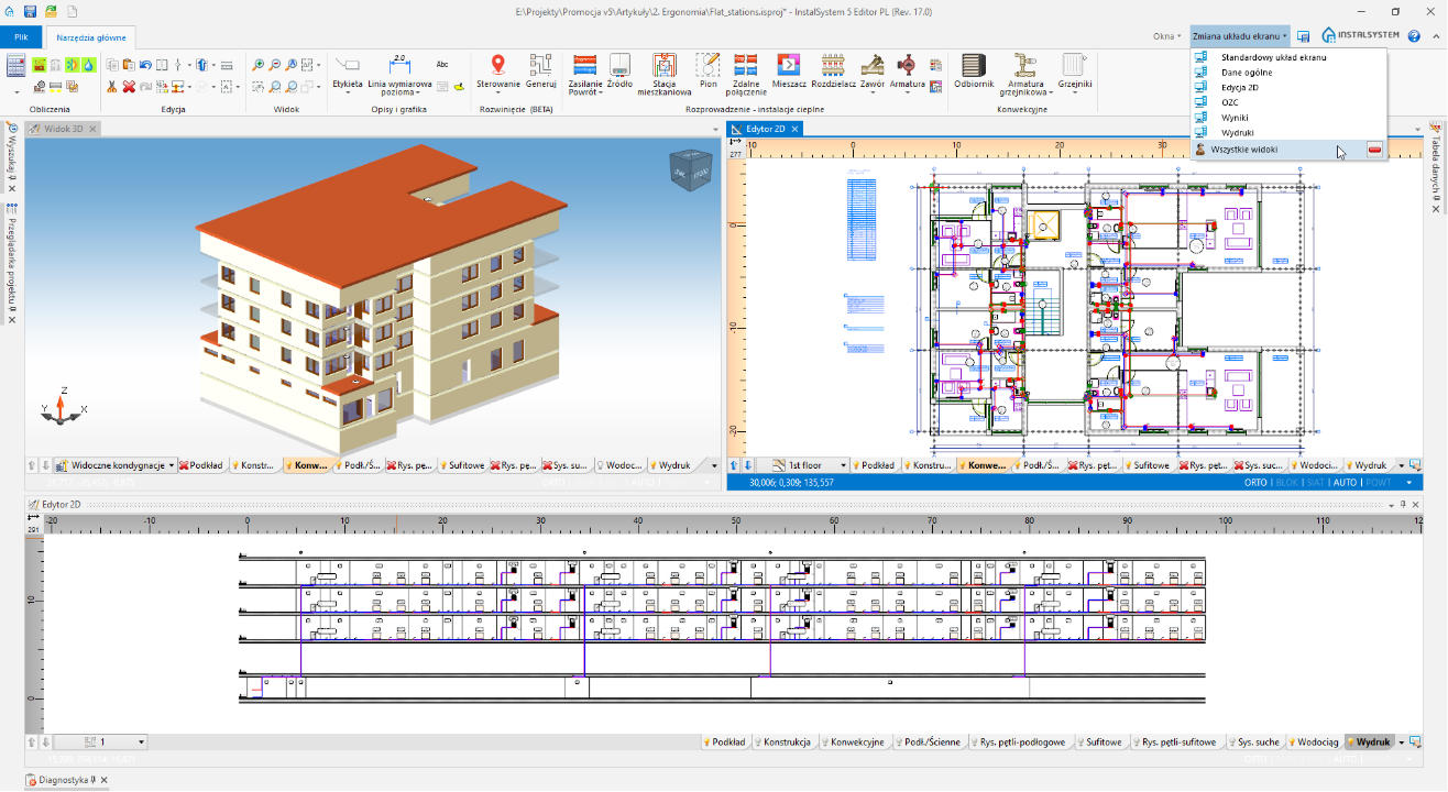
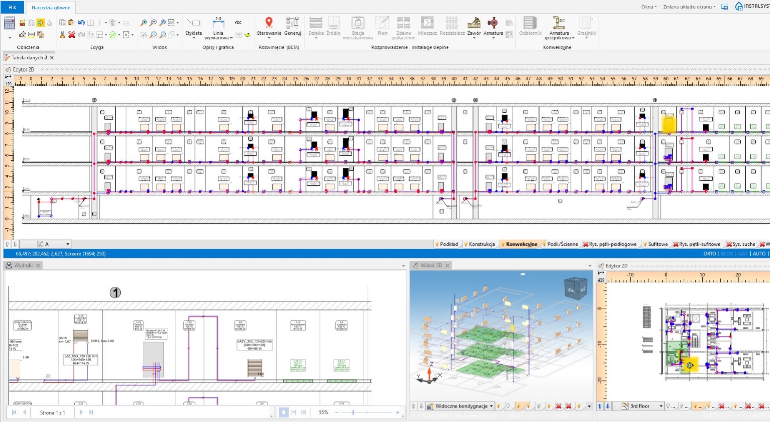
Thanks to the integration of functionality modules in one application, there is no need to switch between different programs all the time.
In order to design or verify an already designed installation project, you just need to switch the editing scope. Configurable visibiiity of particular editing scopes (with visible systems being designed) allows to easily predict and remove collisions. Moreover, an underlay or a prepared building structure, once they have been loaded, are used to create a complex project containing various types of systems. Drawing printouts may include all the designed systems or a part of them.
Read more…

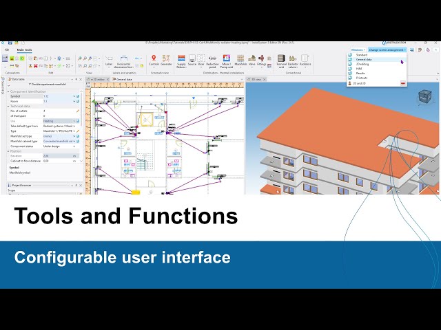
Configurable user interface
Thanks to the possibility of configuring and saving various window layouts, it is possible to optimally plan and position all program windows.
For each of the subsequent stages of the project implementation, by saving and then selecting the appropriate composition from the list, you can quickly obtain the arrangement that makes work most comfortable and effective. The most frequently used functions and tools may be assigned keyboard shortcuts. Similarly, the set of functions visible after pressing the right mouse button is fully customizable.
Read more…
General data and project templates

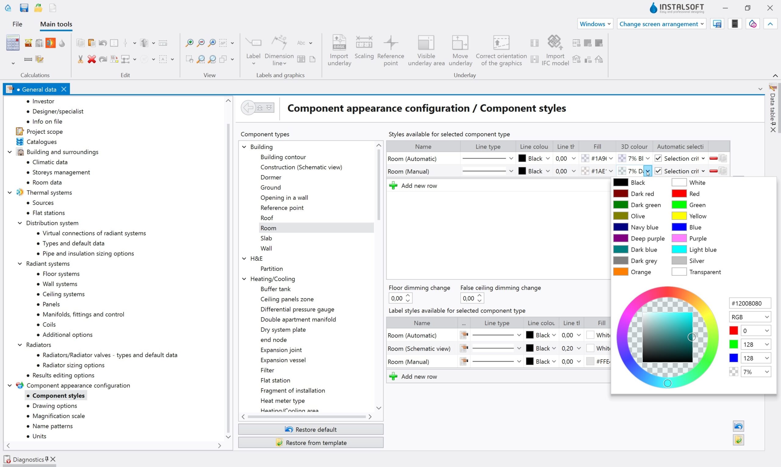
Set of project default data, optionally together with graphic elements, can be saved as project templates.
In this way, having created an appropriate number of predefined templates for typical designs, the designer avoids the necessity to multiply the same preparatory activities before starting work on next designs. Thanks to the hereditary system, general data are propagated to system elements introduced in the design. The “computer” or the “pencil” symbol displayed next to a given data field informs us whether the value comes from general data (or catalogue data) or it has been modified individually.
Read more…

Filters and catalogue browser
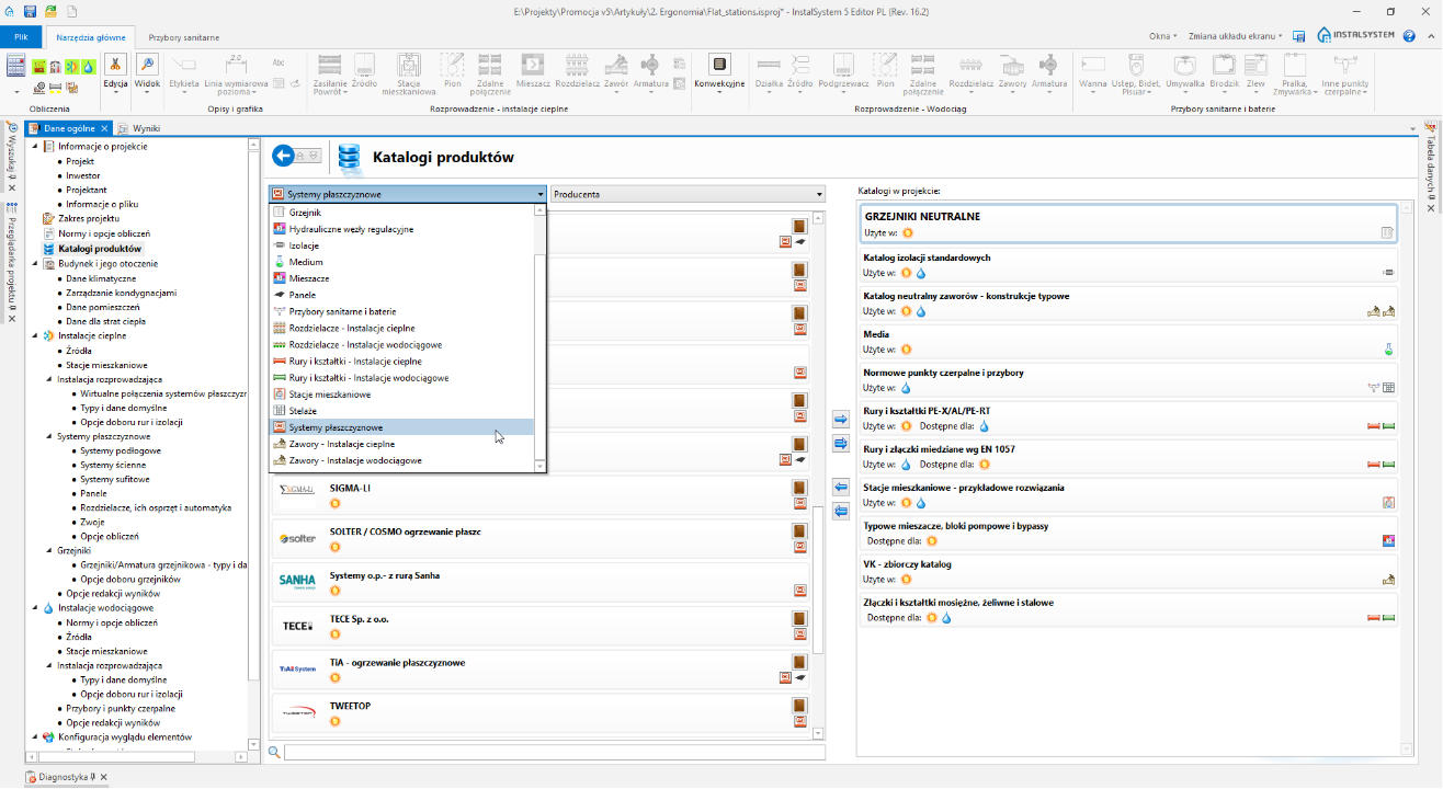
The InstalSystem 5 package has been equipped with hundreds of product libraries for system designing.
It is much easier to find the proper one thanks to advanced catalogue filters, which limit the number of displayed libraries to those containing a given product group (e.g. radiators, flat stations, valves for sanitary systems etc.). As an alternative, one may use the catalogue browser by entering a proper sequence of symbols (e.g. system, product or producer name). Icons presented in the right-hand side of each catalogue inform about element types included in the catalogue and about availability of additional graphical information on the products.
Read more…

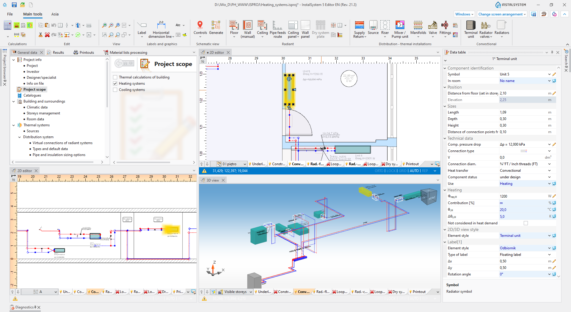
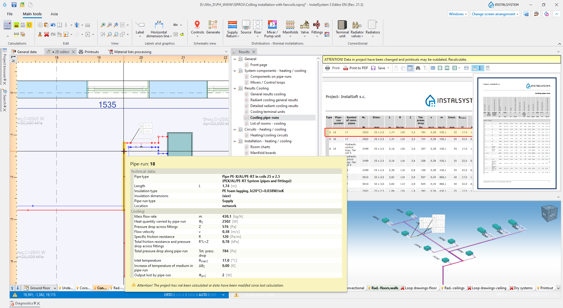
Interactive connection of program windows
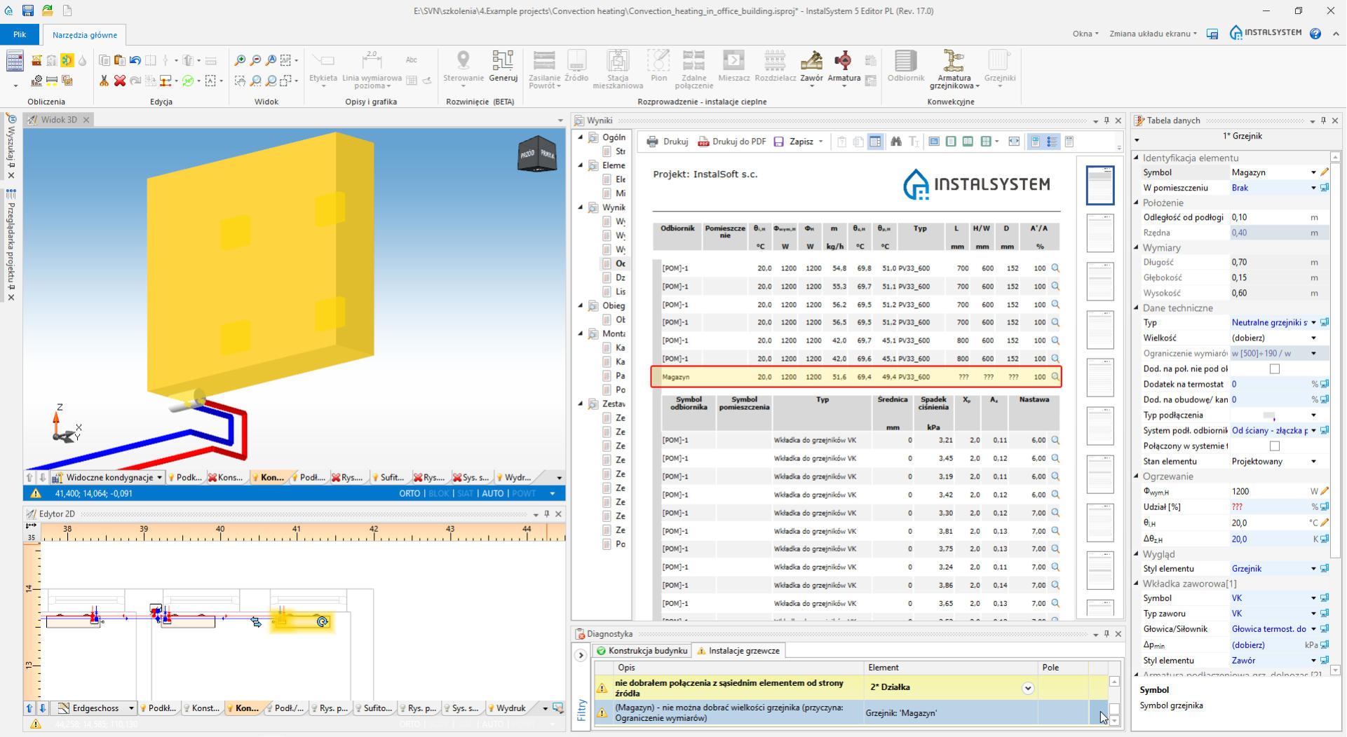
Interactive connection of program windows allows to quickly find and highlight a chosen system element in all active program windows.
It can be done in the plan view, in the schematic view, in the 3D view or in the results table. Additionally, having placed the cursor on a given element, a hint with particular technical data and parameters is displayed. It facilitates the analysis of a given project, its calculation results and makes it easier to find the reason of issues shown by the program diagnostics.
Read more…

Hints on resolving typical design problems
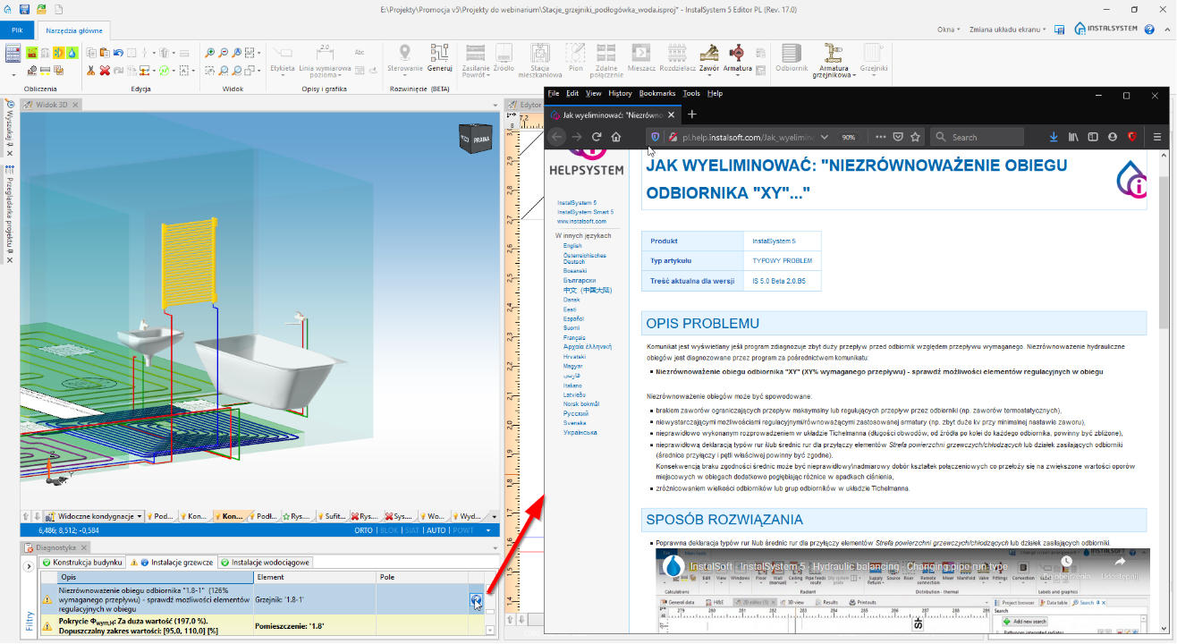
In case often-type errors or problems are diagnosed, the program sends the user directly to the HelpSystem platform articles with dedicated links.
Such articles include typical problem reasons and hints on how to resolve them. The article opens automatically after having clicked the “?” symbol next to a given diagnostics hint.
Read more…
Graphical and textual information on products
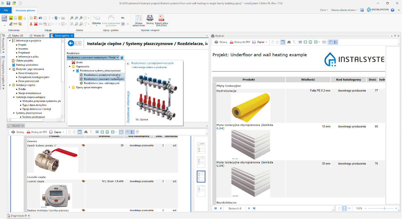
Additional possibility to display images of whole systems and their parts along with information from the producer’s website.
It facilitates the choice of the right product. Material list printouts may also contain photos as well as additional element description, which renders the design documentation much more complete and visually attractive.
Read more…

Easy and fast access to older versions of the program

During the first phase of file opening, the program recognizes the version on which the file has been saved.
By choosing the newest or an older version of the program, the designer gains control on the status of the application which runs the calculations and material list, he/she also controls the product libraries to be used in the design. In such a way, the problem with the lack of access to products, which may be eliminated during the work on a given project for the manufacturer’s assortment changes, has been eliminated.
Read more…
64-bit architecture
The new software generation uses the full 64-bit architecture and the newest graphics engines.
Never before have the InstalSoft programs been working in such a smooth way with such large objects (over 100 mb). With accurate hardware, you will have the opportunity to work with the most demanding objects. It also concerns objects of BIM-process provenance. Also various standard editing operations have been accelerated, and the calculation time has become 50% more optimised.
Read more…
Design process automation
System models, currently designed in engineering programs, should carry data and parameters that allow the program to perform complex calculations. In the past, these calculations were performed independently from the graphical design. Some phases of the project, necessary to obtain a complete computational model with design documentation, were labor- and time-consuming, while model corrections were very problematic – until now. Thanks to our long-standing cooperation with industry designers and the creativity of InstalSoft engineers, many of these phases have been enhanced and automated. Read about just some of the improvements.
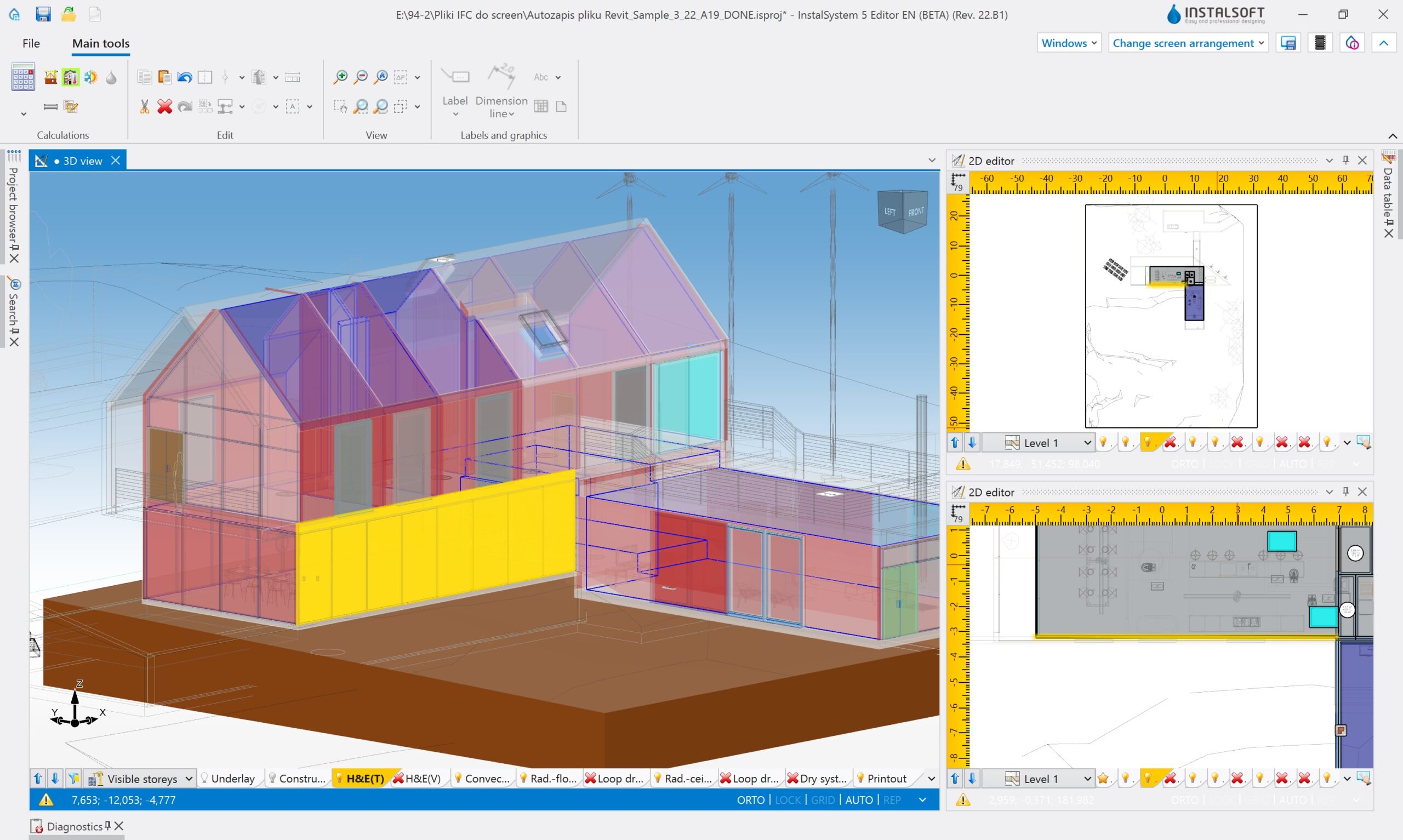
3D building structure and system model
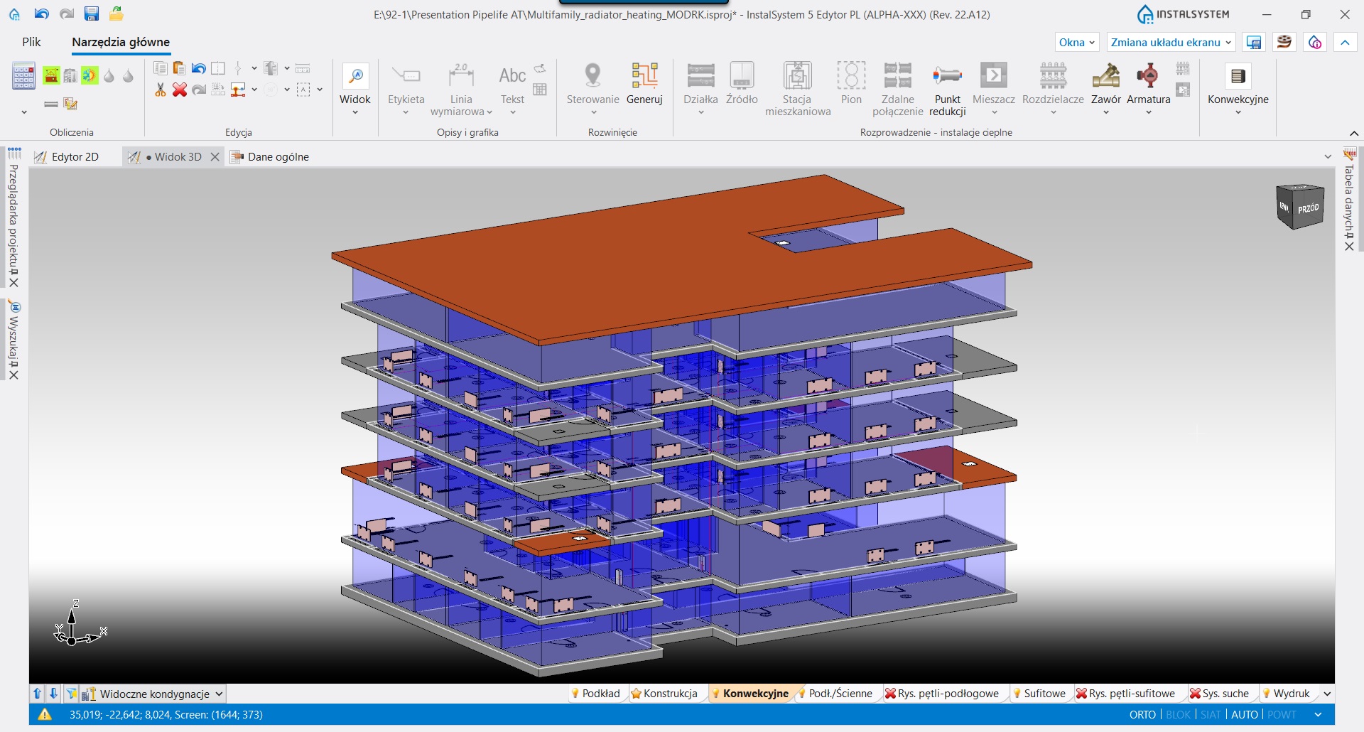
3D model in the InstalSystem package is created automatically on the basis of plan view designs and other data of particular elements.
New additional tools support and accelerate the creation of a 3D model, among which: general data, possibility to copy whole storeys (or system fragments on storeys above/below), stack risers covering appropriate storey scope automatically. The 3D model allows us to open up to the BIM process.
Read more…
Building structure preparation

The procedure of building structure preparation in the InstalSystem 5 package is similar to the real process of creating a building structure, it is also very fast and intuitive.
Having prepared the rooms and the building contour as well as having run the function “Automatic walls, slabs and roofs” all walls, interstorey slabs, roofs and floors are generated automatically. For such a generated building body, you just have to insert a roof, windows and doors, thus obtaining a complete building structure. We also allow our designers to use the highly automated process of obtaining the building structure out of IFC files.
Read more…
Calculation of heat loss for rooms and buildings
Based on heat partition definition, the InstalSystem 5 package automatically assigns heating parameters to accurate design partitions.
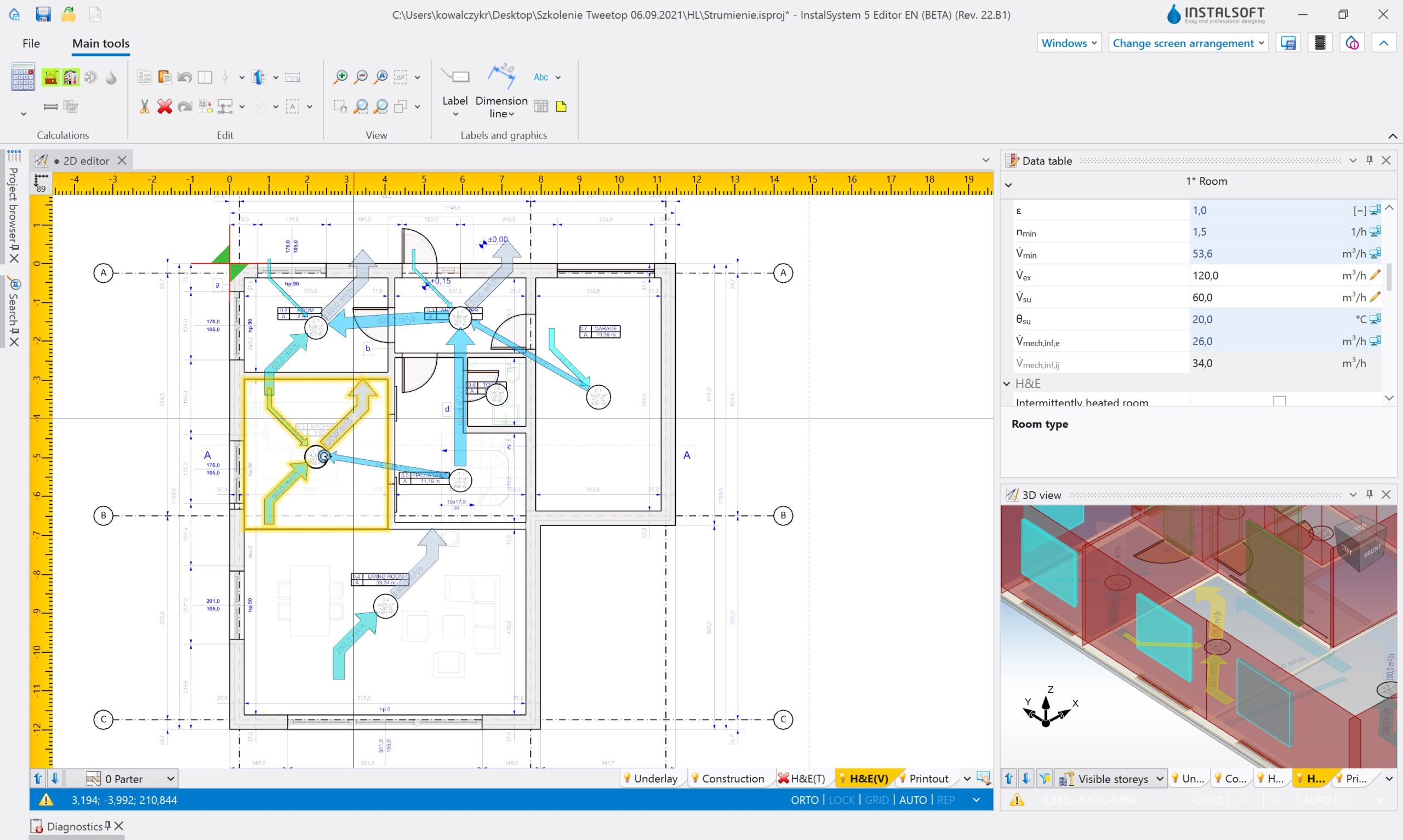
Interstorey slabs are divided into separate heat partitions when they are situated above a number of rooms with potentially different internal temperature (the roof is divided analogously). In buildings with cellars, the part of wall laying below the ground is detected automatically, and the “Ground modeling” function allows to define external walls in contact with the ground in a precise manner. In order to facilitate the analysis of ventilation airflow, a balance and a diagram of ventilation airflow with airflow values are created.
Read more…
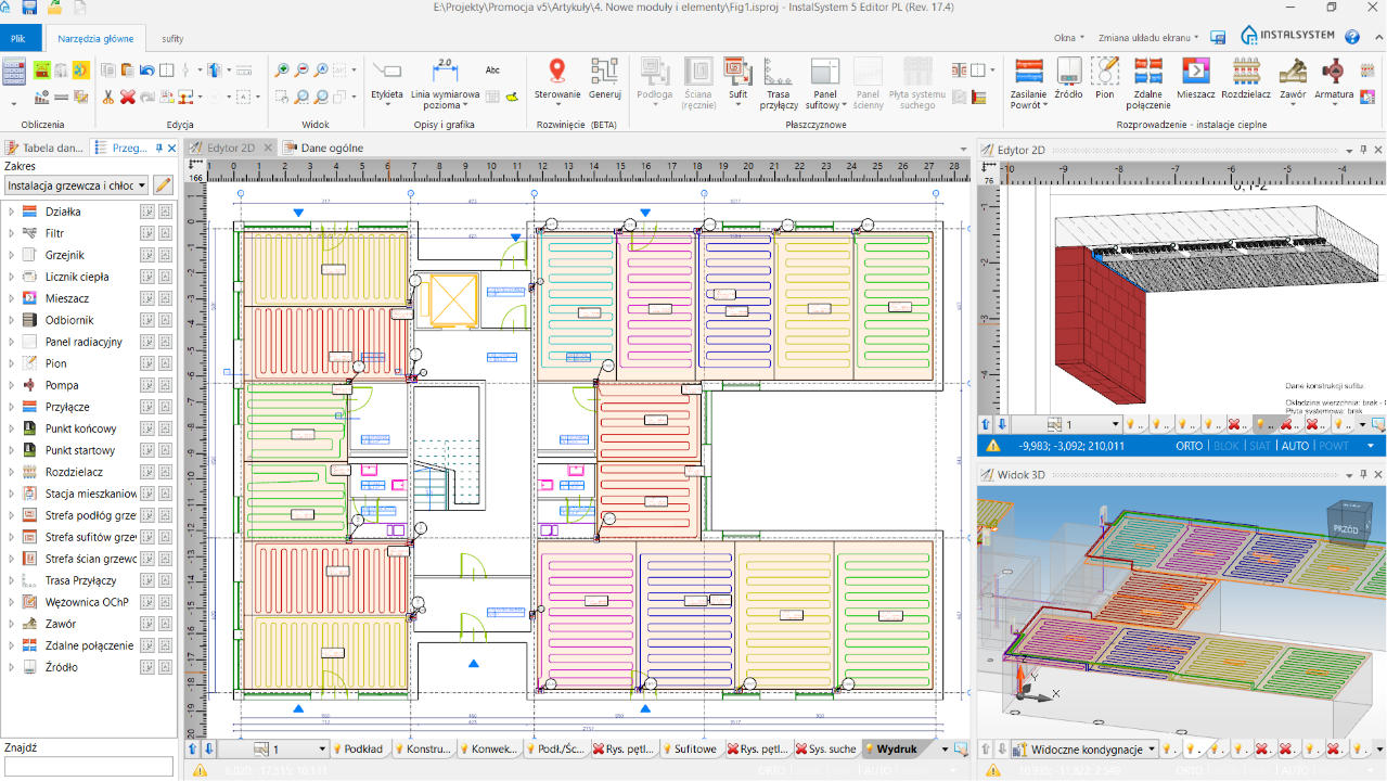
Division of heating/cooling zones into required number of loops
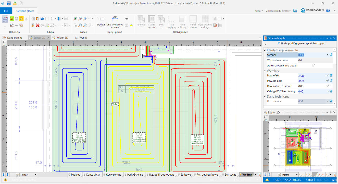
After inserting heating/cooling zones, the InstalSystem 5 package divides them into a required number of loops automatically.
One of the division criteria is “according to equal pressure losses” – it is particularly useful wit large spaces, in which the medium is Tichelmann distributed (without flow regulation at the manifold). The division of zones according to this criterium allows to obtain a similar loop length (in manifold systems including loop length) in all circuits.
Read more…
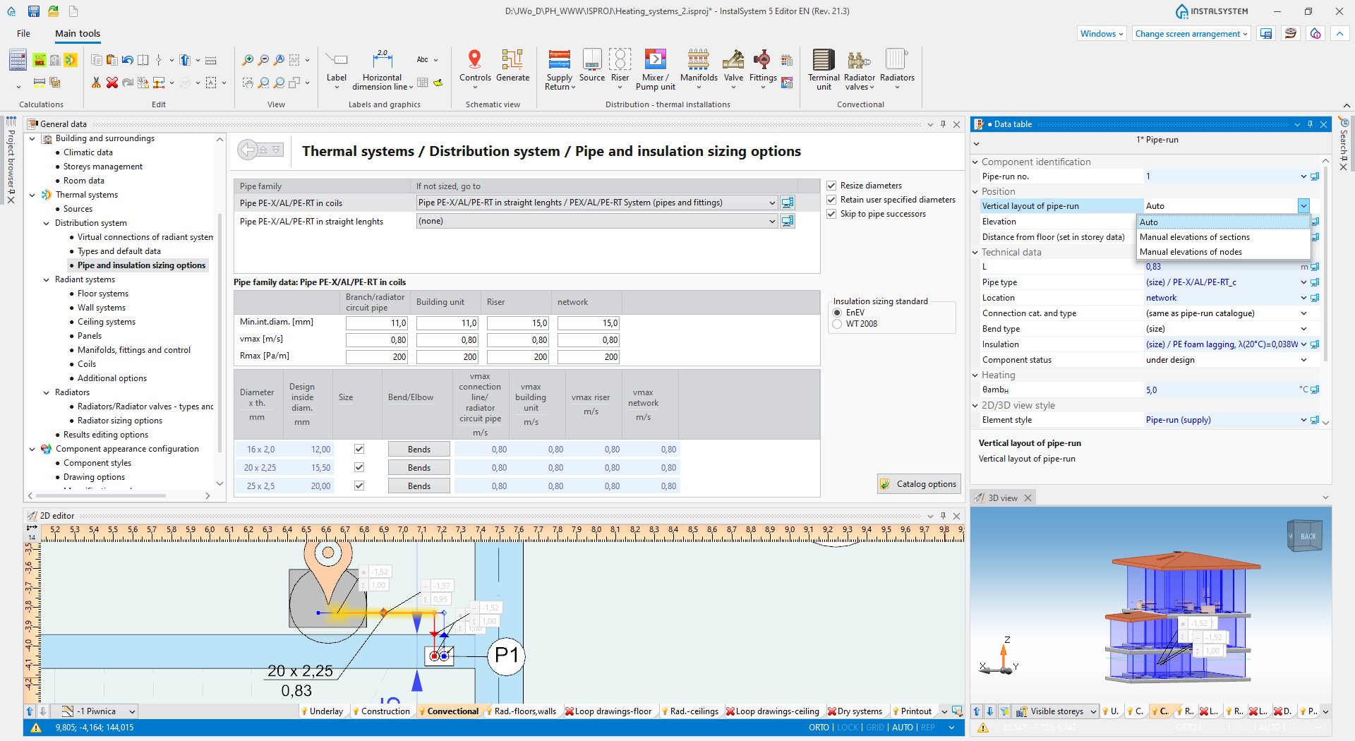
Designing of loops between the manifold and heating zones
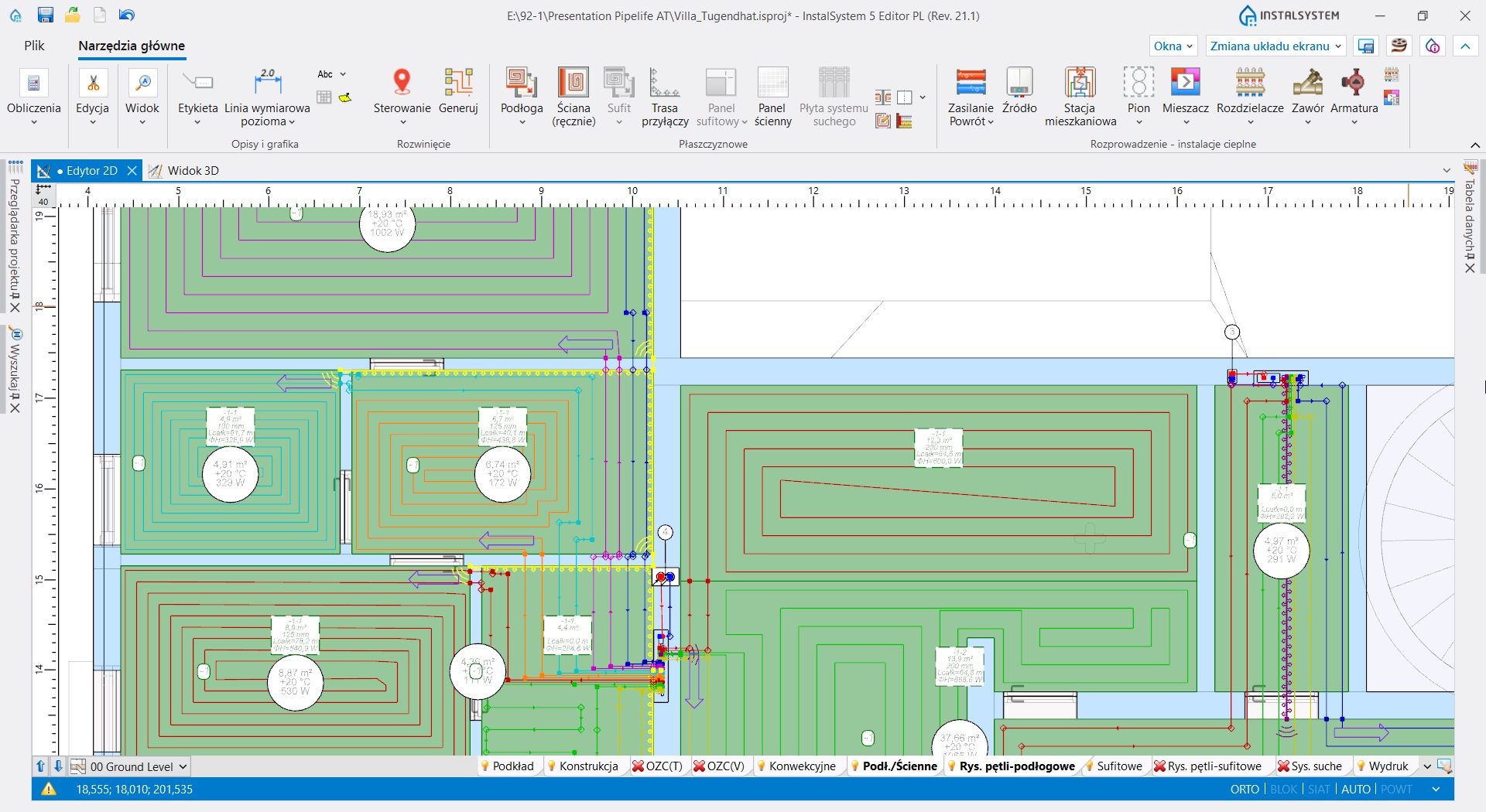
For an indicated pipe feed route, the InstalSystem 5 package generates such feeds in a required amount and with correct pipe spacing automatically.
All the modifications in the design, which result in a change of the required pipe feeds or spacing between them, generate correct pipe feeds.
Read more…
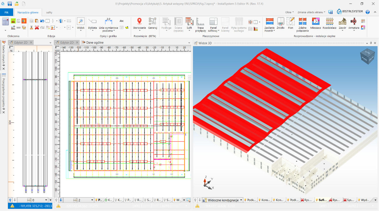
Panel / ceiling panel systems arrangement
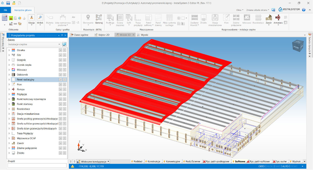
“Panels zone” allows to fill the whole ceiling zone or its section with radiant panels.
Such automation is performed based on the manufacturer’s guidelines (stored in the program libraries) or the program user.
Read more…
Generation of system schematic views
Having created a system with use of plan and 3D view, it is possible to generate schematic views in (literally!) few mouse clicks.
Thanks to all available tools, you may easily steer the particularity of information presented in the schematic view.
Read more…
Design documentation
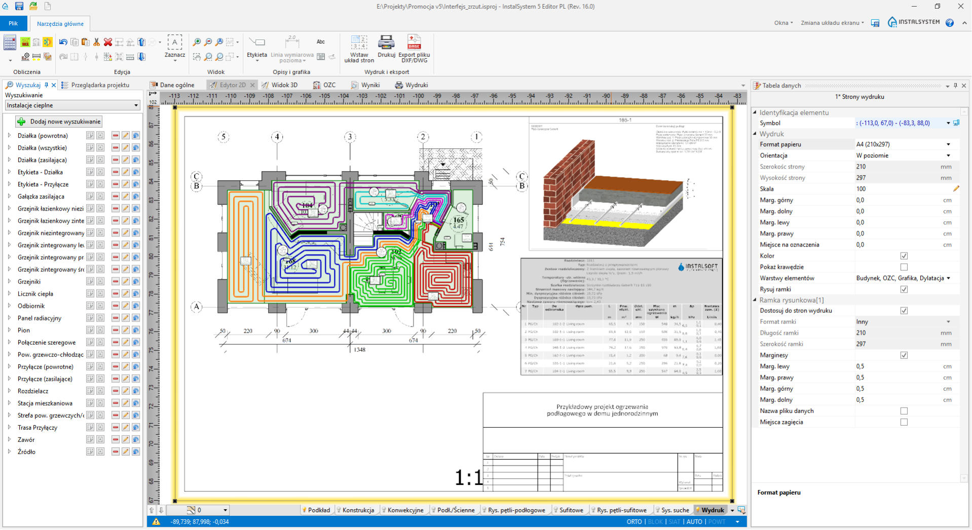
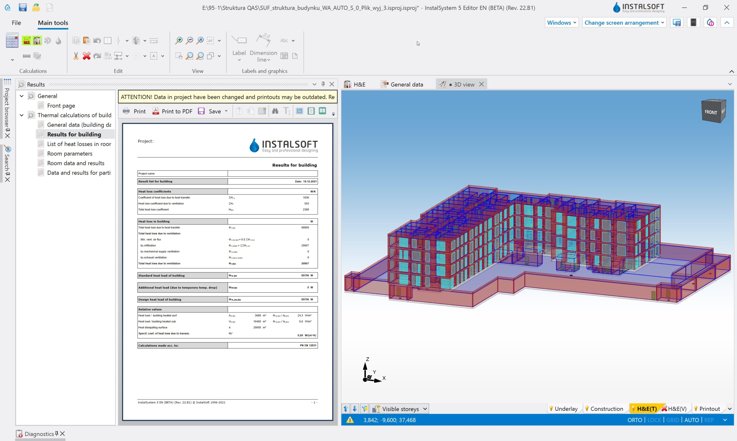
All design documentation elements are generated automatically with the possibility to modify both style and scope of presented information.
Starting with floor and ceiling heating-cooling system loops and finishing with additional graphical information, such as element labels, graphical cross-sections of radiant systems, and manifold or design tables.
Read more…
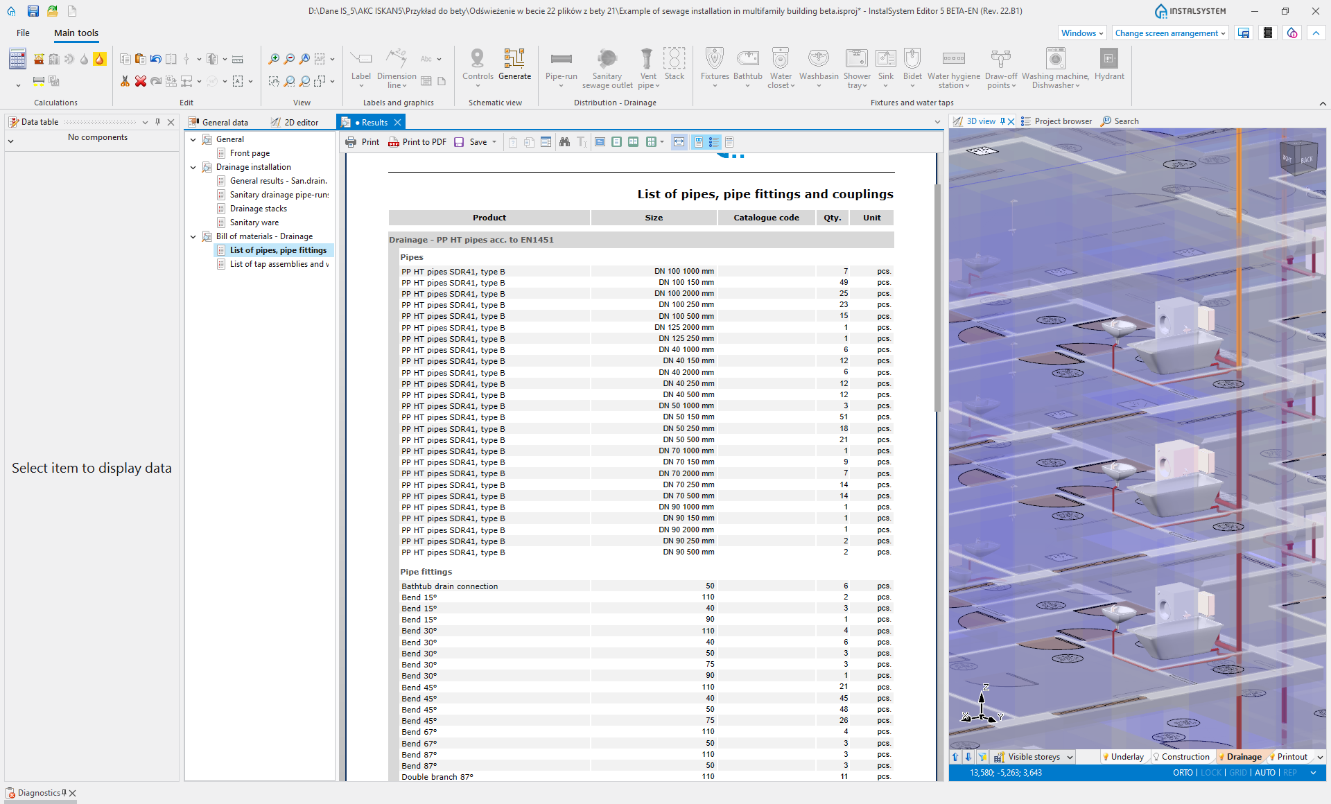
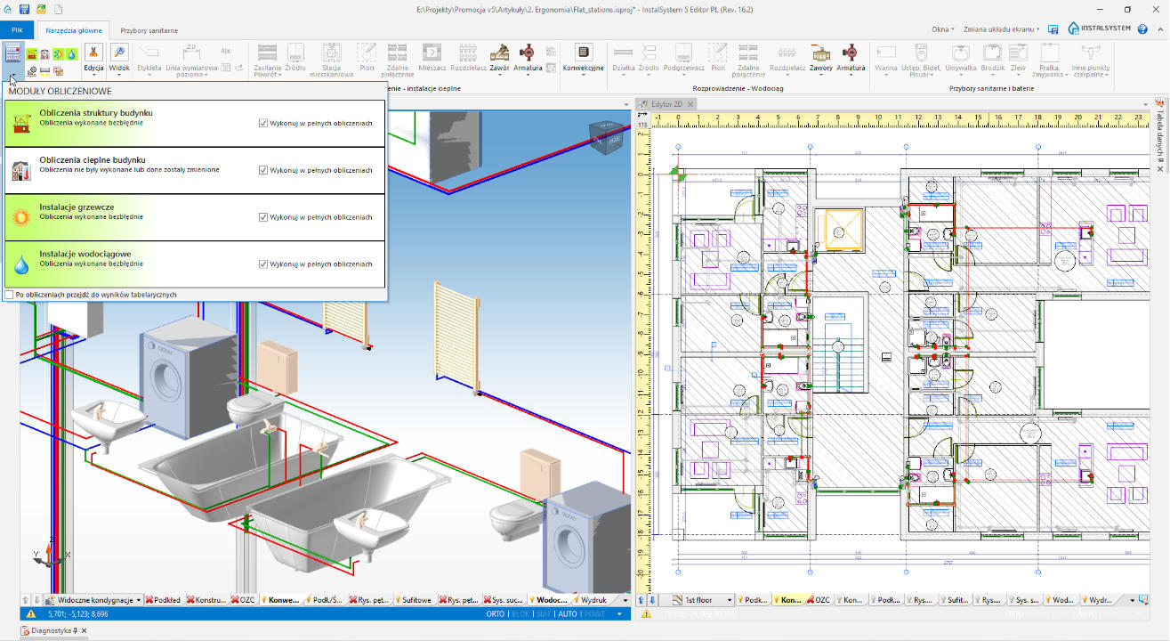
Calculations and material list

Just one click runs complex calculations. Their scope depends on the number of modules available in a given configuration.
You can also generate complex material lists containing all elements necessary to create a system with use of manufacturers’ libraries or neutral ones.
Read more…
New functionalities, new tools, new system elements
Design process evolution and the growing popularity of new installation systems, which respond to higher and more differentiated expectations of investors and designers, have resulted in new modules and new installation systems in the InstalSystem 5 package.
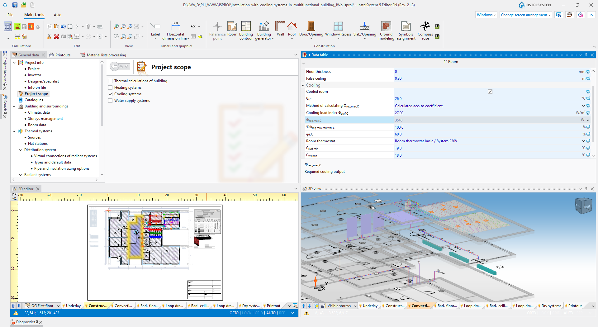
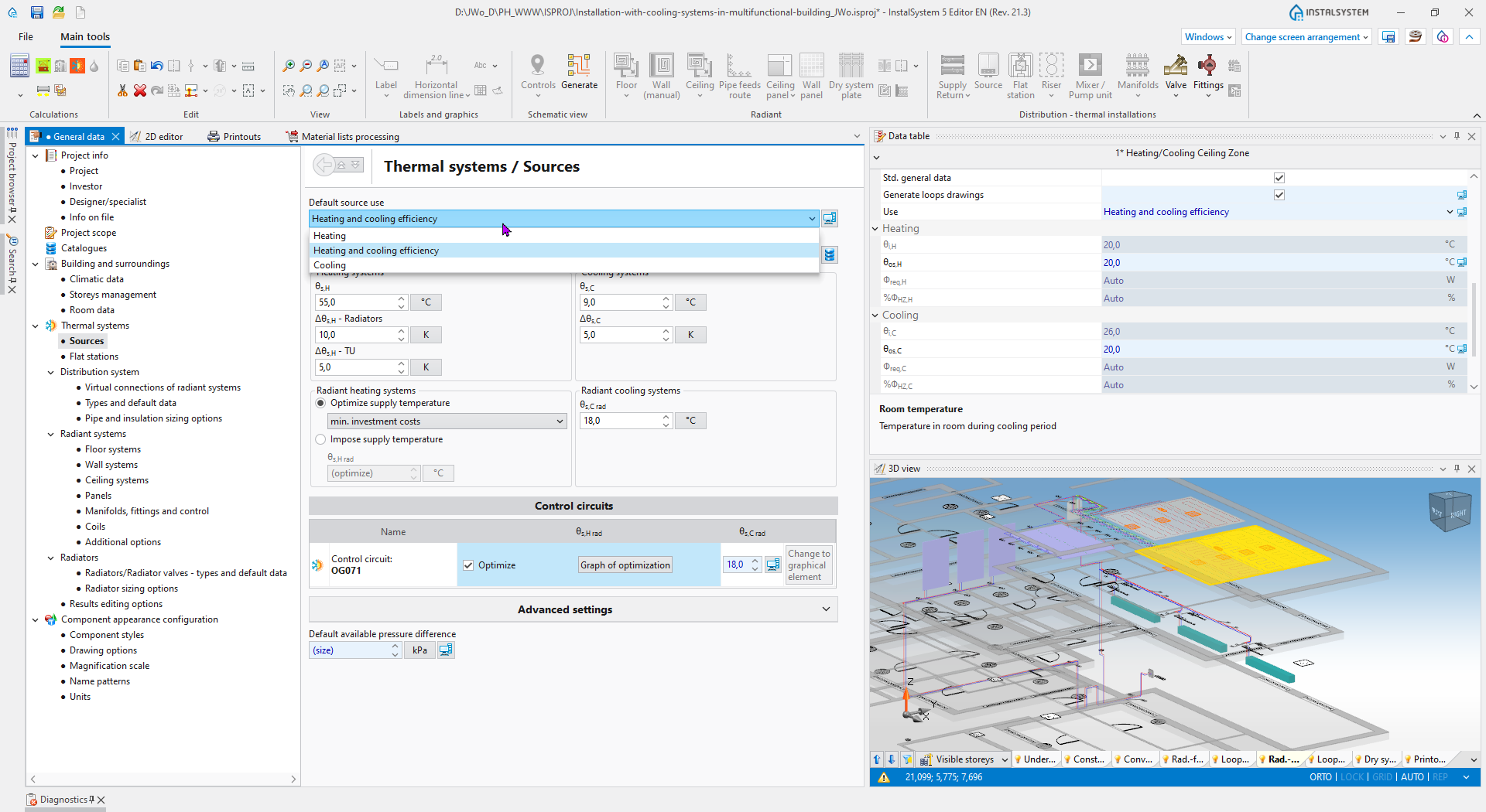
Radiant cooling
We have extended our new generation with the possibility to design radiant cooling systems, which are placed in floors, walls or ceilings.
Depending on the chosen priority, it is possible to size the system and its parameters in order to cover heating demand (with checking cooling output) or, as an alternative, to cover cooling demand. A particular and automatically-created design documentation allows to analyze the system parameters and all elements necessary to create it.
Read more…
Wall and ceiling panels

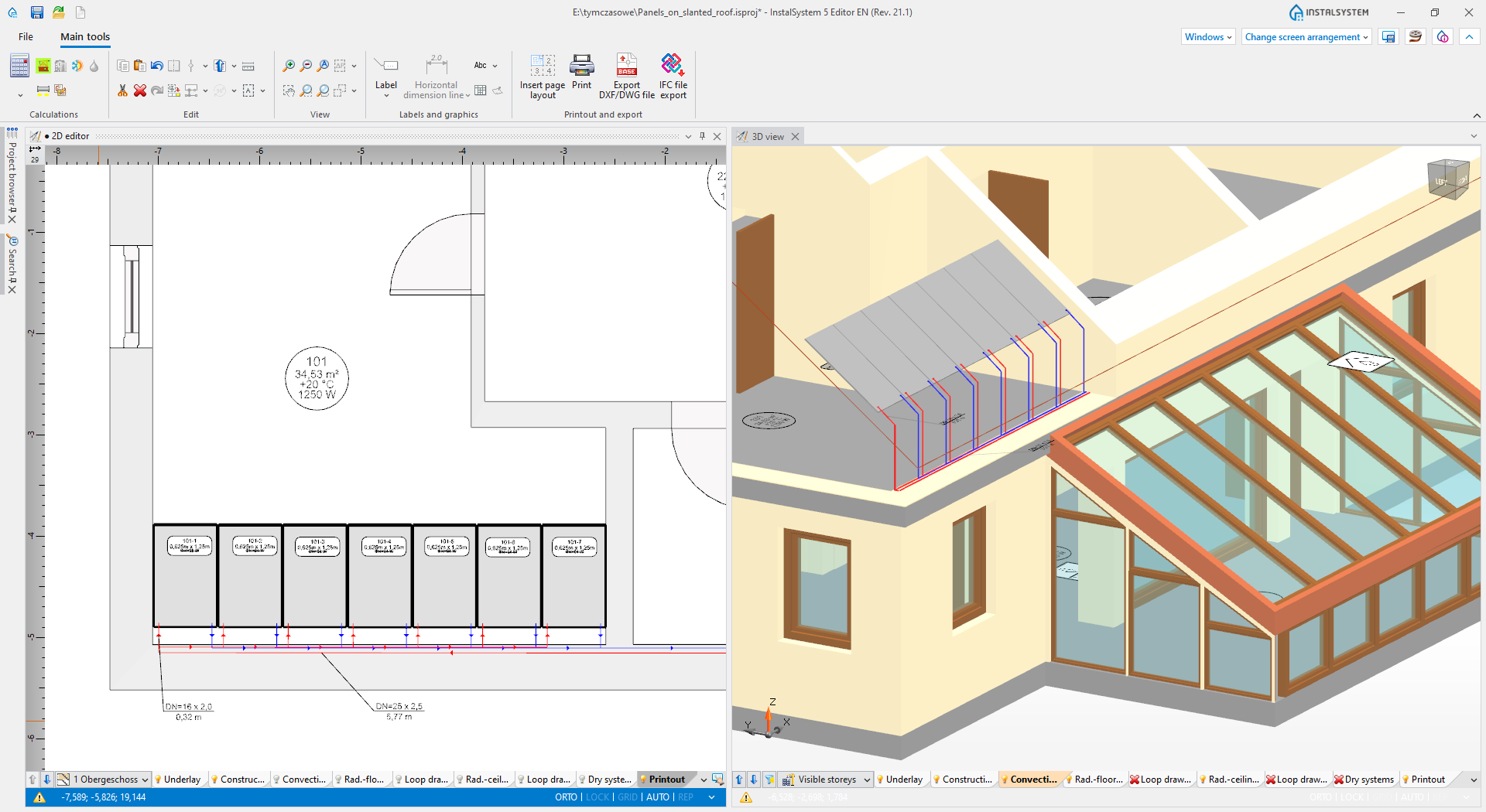
Both in heating and cooling system design, it is possible to use numerous libraries of prefabricated wall and ceiling panels.
Such solutions are much more popular thanks to their easy and quick assembly, lower thermal inertia as opposed to traditional radiant systems, and much more affordable prices. A very interesting and much more commonly used solution is the montage of panels on the slants of habitable attics or lofts, which can also be easily designed with the InstalSystem 5 package.
Read more…
Appended radiant ceiling panels
Based on the producer’s know-how or the designer’s guidelines, a new “Panel zone” located in a chosen place is filled automatically.
The next thing to do is calculating and balancing the flows in such a system in order to achieve the required heating (or cooling) output.
Read more…
Flat stations
Thanks to integrating all computational modules in one InstalSystem 5 package, it is possible to design, as complex as never before, heating and cooling systems with use of flat stations.
Based on the chosen scenario and available computational modules, the required domestic hot water outflow may be defined directly as a numeric value or calculated by the tap water module, based on a chosen calculational norm. Such calculations take also into consideration, among others, dimensioning of the supply system (stack risers, source and heat buffer) including asynchronous functioning of the station in the domestic water heating option.
Read more…
Hydraulic control loops
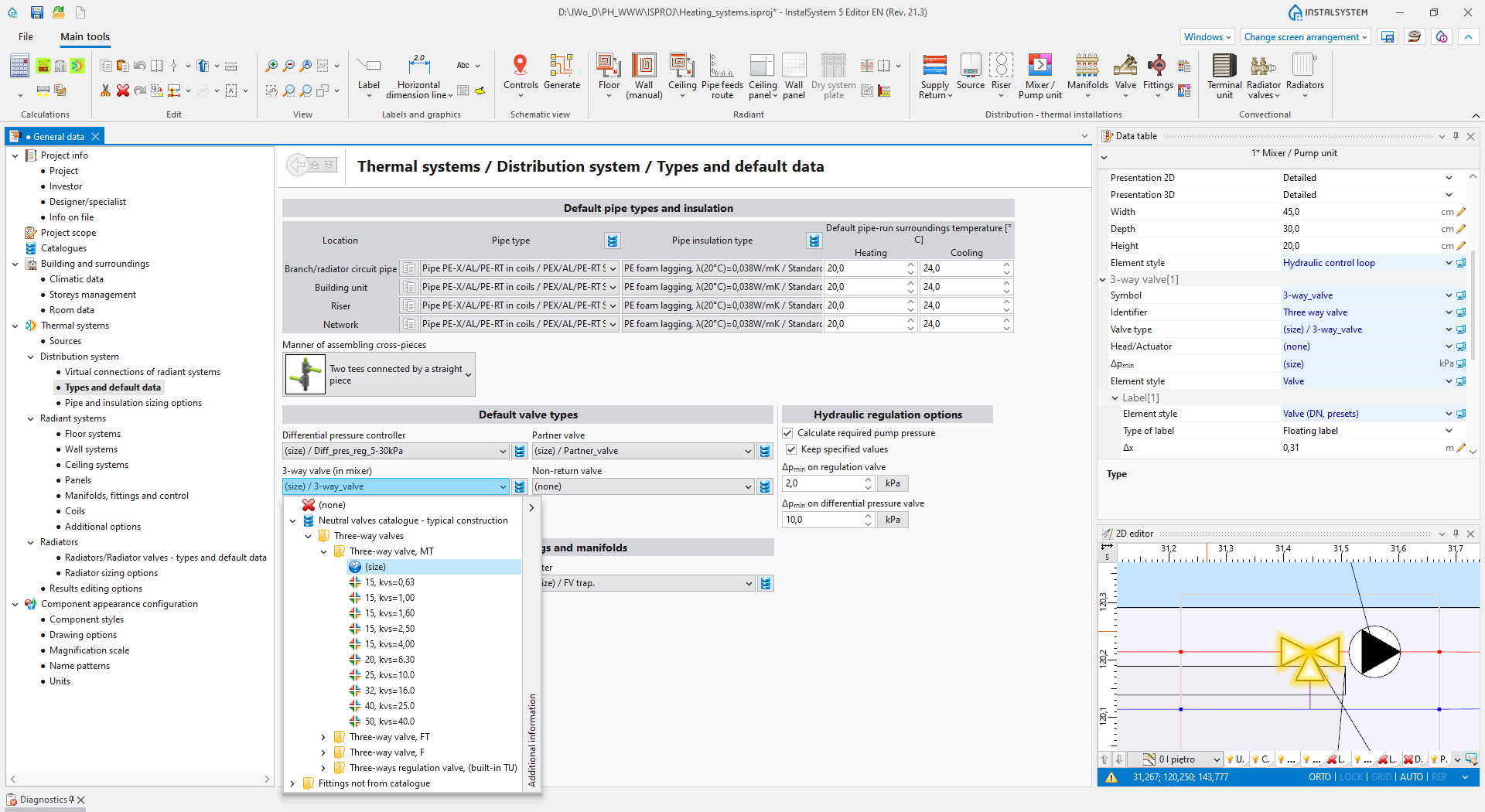
Already available in InstalSystem 4, predefined hydraulic control loops offered by leading armature manufacturers are developed and completed with new possibilities in InstalSystem 5.
Prepared on the basis of the manufacturer’s guidelines, ready-to-use hydraulic control loops take into consideration a number of aspects related to the correct choice of valve types, their sizing, adjusting and required pump-rising altitude. This incredibly advanced and unique functionality allows the designer to prepare a very advanced control system in an incredibly easy way, according to our best knowledge and to guidelines of leading balancing and control fittings producers.
Read more…
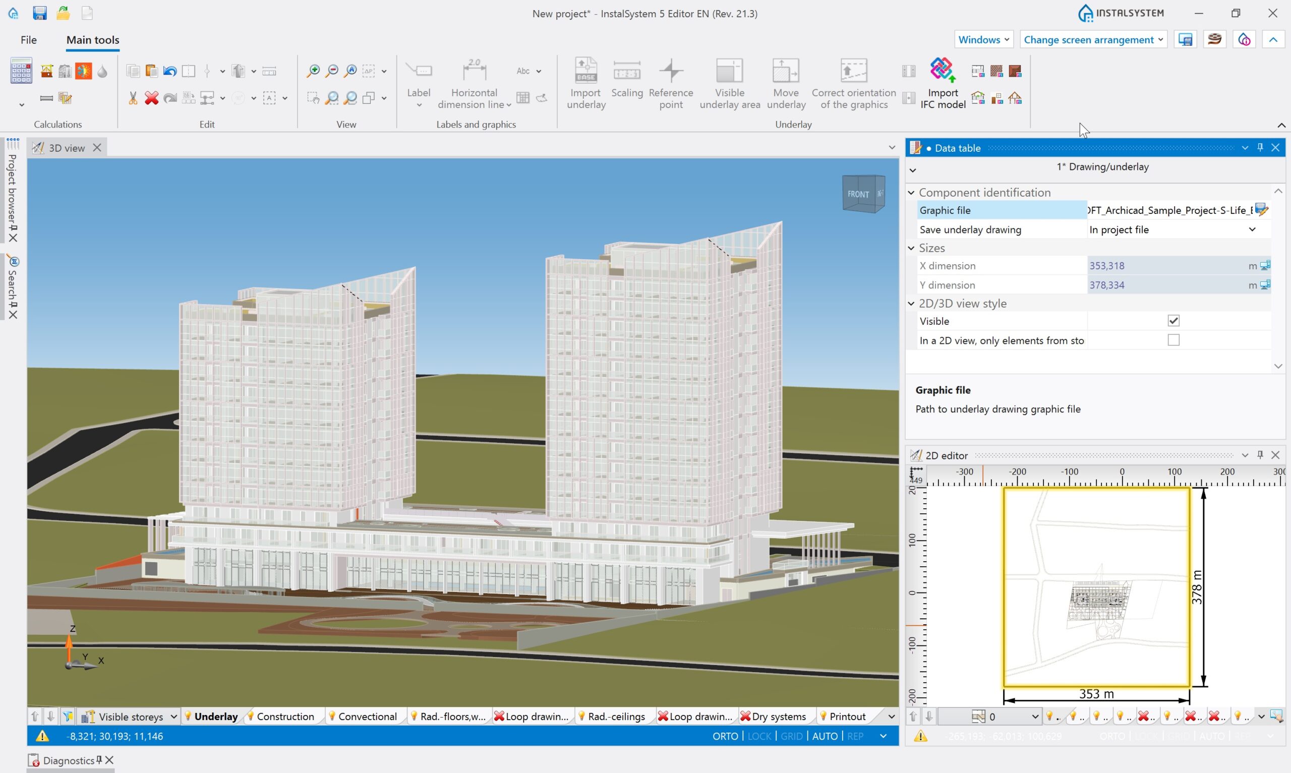
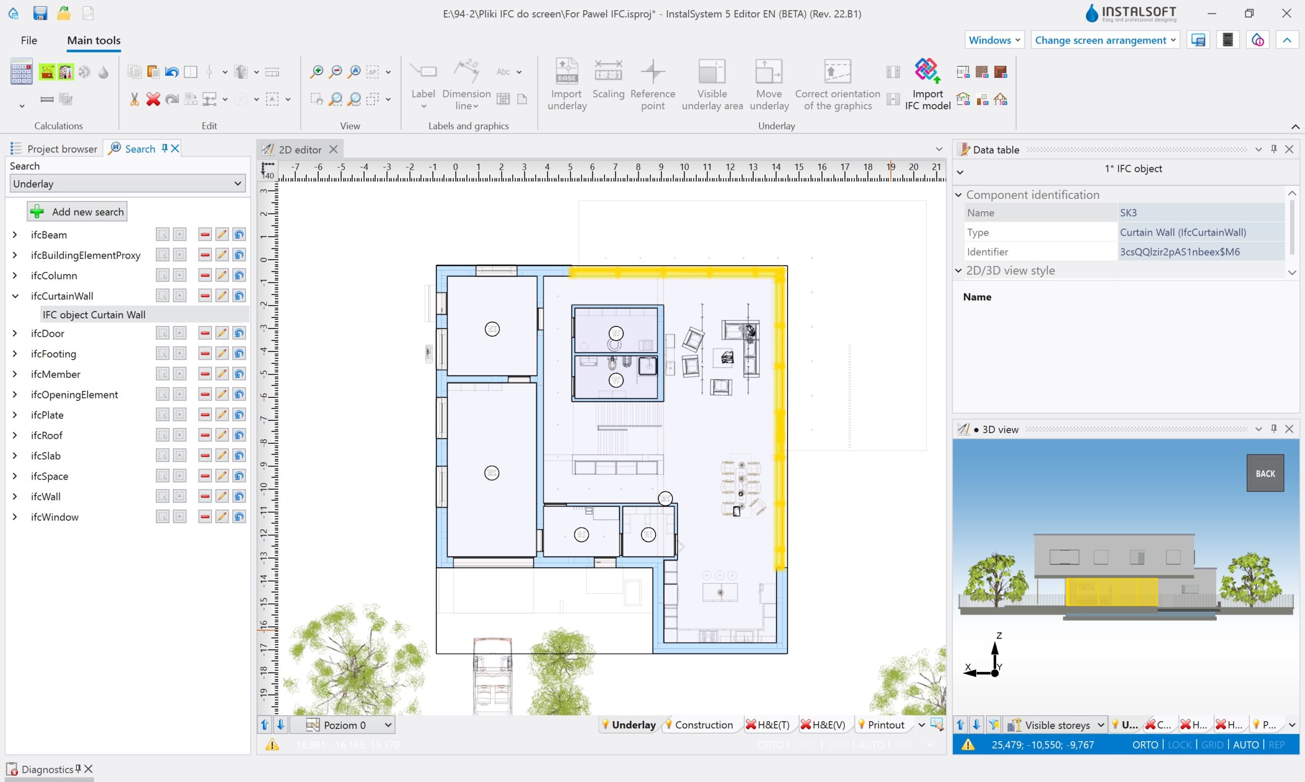
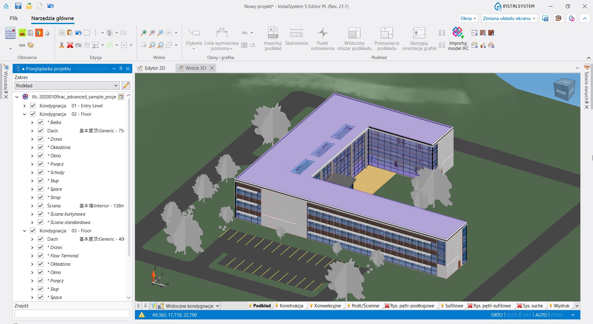
BIM import

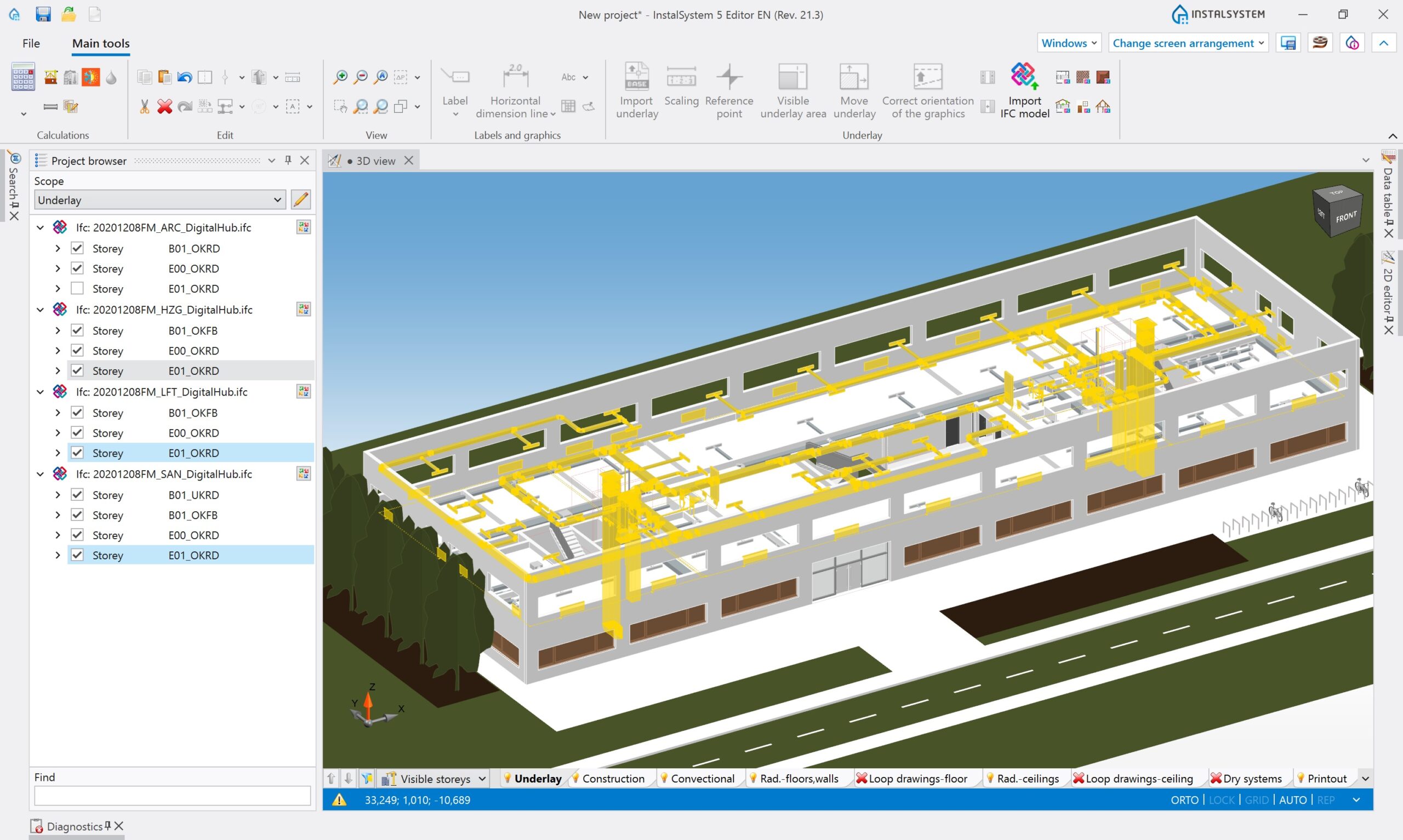
The InstalSystem 5 package has undergone a revolution in order to be adapted to the Open BIM idea. Thus, the program fully supports IFC2x3 and IFC4 format files.
The designer may load a random number of files, he/she may remove them or replace them, which is essential in the BIM process. Management of the imported model is possible thanks to the dedicated design browser and to information visible in the data table. Model objects may be highlighted or hidden. They are also visible for the SNAP function while editing other scopes in the 2D Editor. Models loaded with use of this module may be interpretated in regard to the building structure, which may be then modified freely.
Read more…
Dry system boards arrangements module

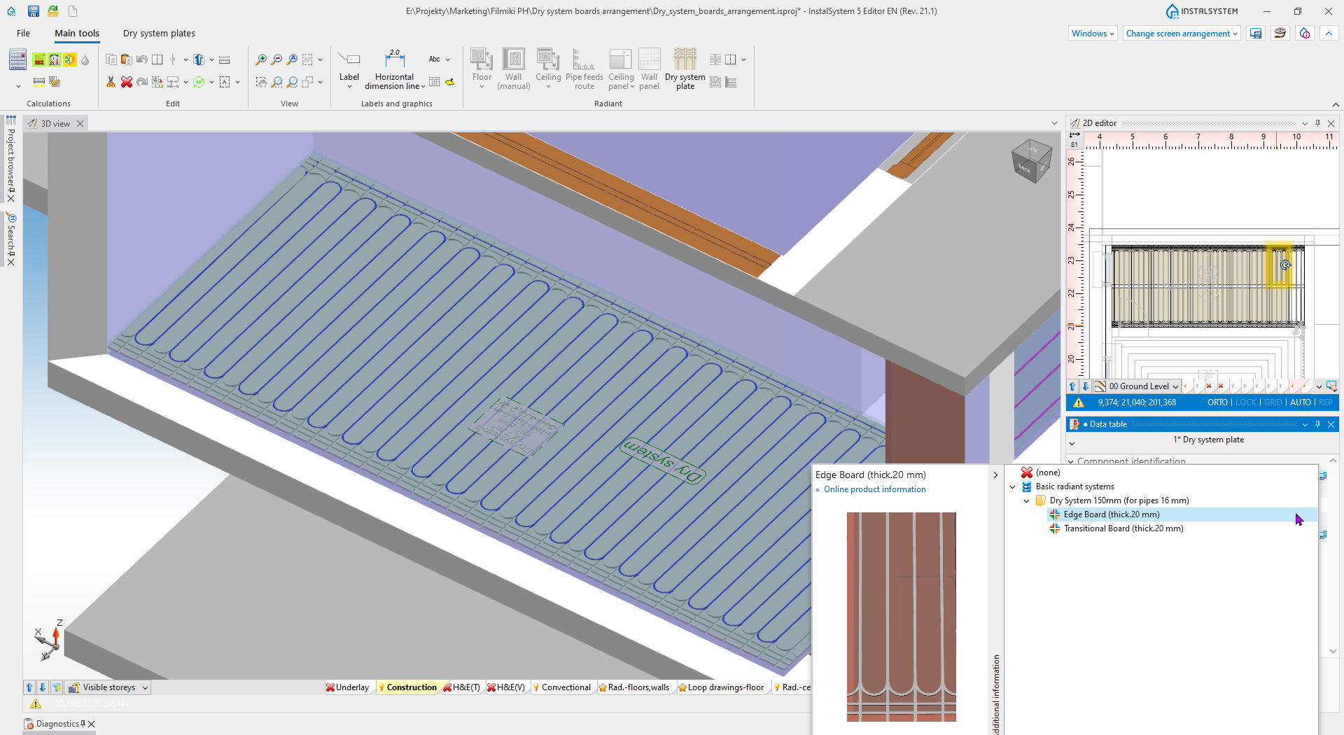
Dry system boards were already available in the previous InstalSystem generations. A novelty in the version 5 is that the module allows to arrange such boards manually.
Using board types available in a producer’s catalogue, with help of the program working modes (AUTO, ORTO), it is possible to arrange and match boards in rooms, after which radiant heating loops should be laid down in them. For such a system, the program runs complete heating and hydraulic calculation. As cutting and further usage of such boards is possible, the material list contains no excessive elements.
Read more…
BIM export

The program exports system designs and structure building elements, created in InstalSystem 5, into IFC format, thus supporting the BIM idea.
The building structure is exported based on the 3D model of the building and is part of the IFC Reference View export method defined by buildingSMART. The export contains basic information about the name of objects and their properties, as well as an exact geometric representation of the objects. The new, dedicated window “IFC file export” allows to export or exclude from export element labels, define the scope of exported elements or choose sheets to be exported, and to define number of IFC result files. IFC model export may be done in an iterative manner, according to the BIM process.
Read more…
Energy certificates (PL market)
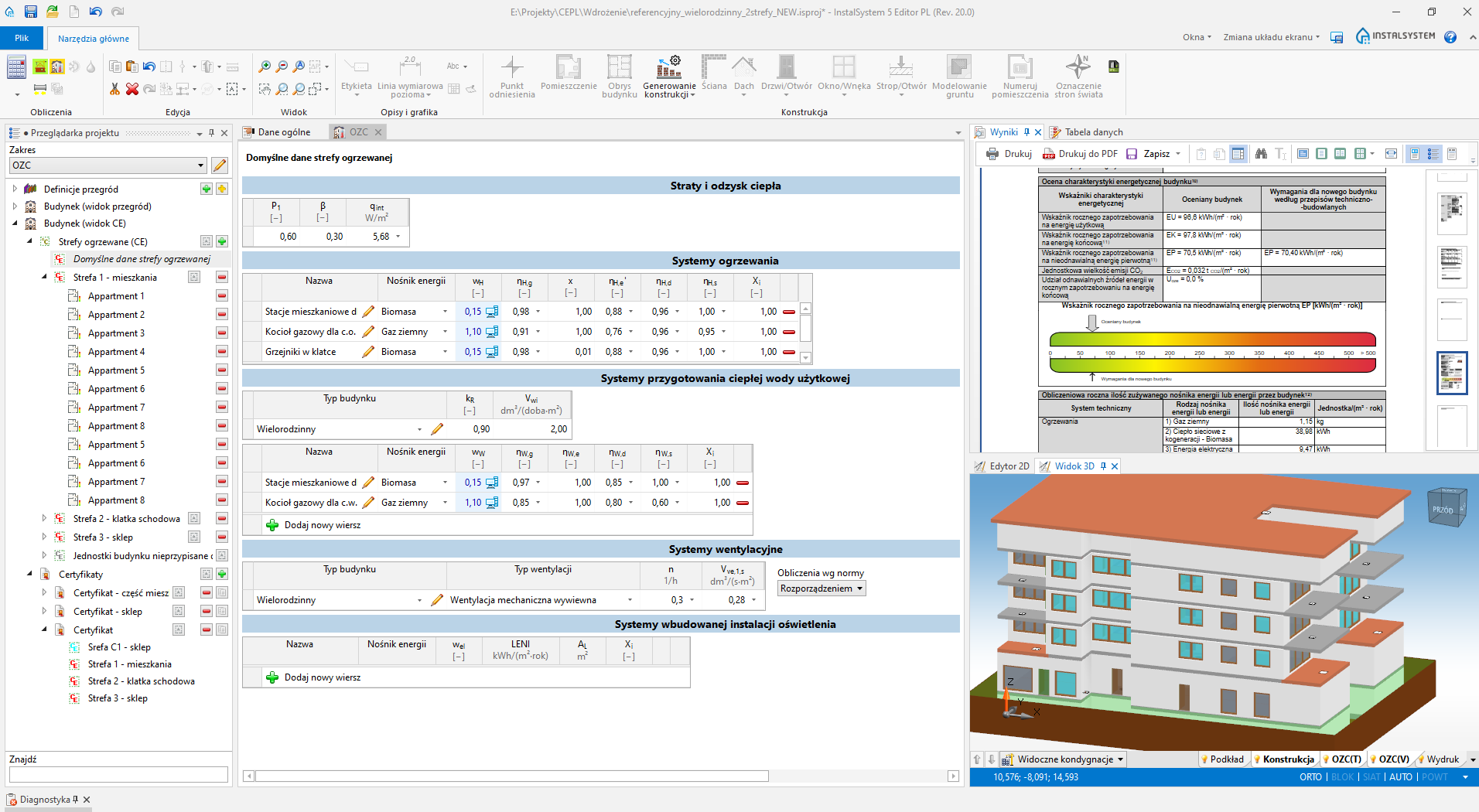
The possibility to prepare energy certificates and characteristics for buildings and a detailed printout of designed energy characteristics of a building.
The module has been extended with the possibility to take into consideration cooling systems and with the Export button (available in the Printout and export ribbon), which allows to export the certificate into an XML file in order to import it into the central register of energy performance certificates. The program allows to perform it both based on WT2017 and WT2021.
Read more…
Technical support
We know how important is to support work of our Partners and Designers with such extensive software as InstalSystem 5.

Free help system in form of online articles

Tens hours of materials that show the program's possibilities step by step

Complex program of individual and group training in basic and advanced scope

Free support available 5 days a week

List of functionalities, tools and modules provided with each publication

Minimum and recommended hardware requirements for InstalSoft software

Current list of supported standards in InstalSoft packages
Do you have any questions? Do you need personalized offer? Contact with us!